Model 239wm-002 stanchion, Voip/wifi telephone wiring – GAI-Tronics 239WM-001 Slim Wall-Mount Stanchions User Manual
Page 7
Pub. 42004-476A
Model 239WM-001 & 239WM-002 Slim Wall-Mount Stanchions
Page
7 of 9
e:\standard ioms - current release\42004 instr. manuals\42004-476a.doc
08/14
Model 239WM-002 Stanchion
VoIP/WiFi Telephone Wiring
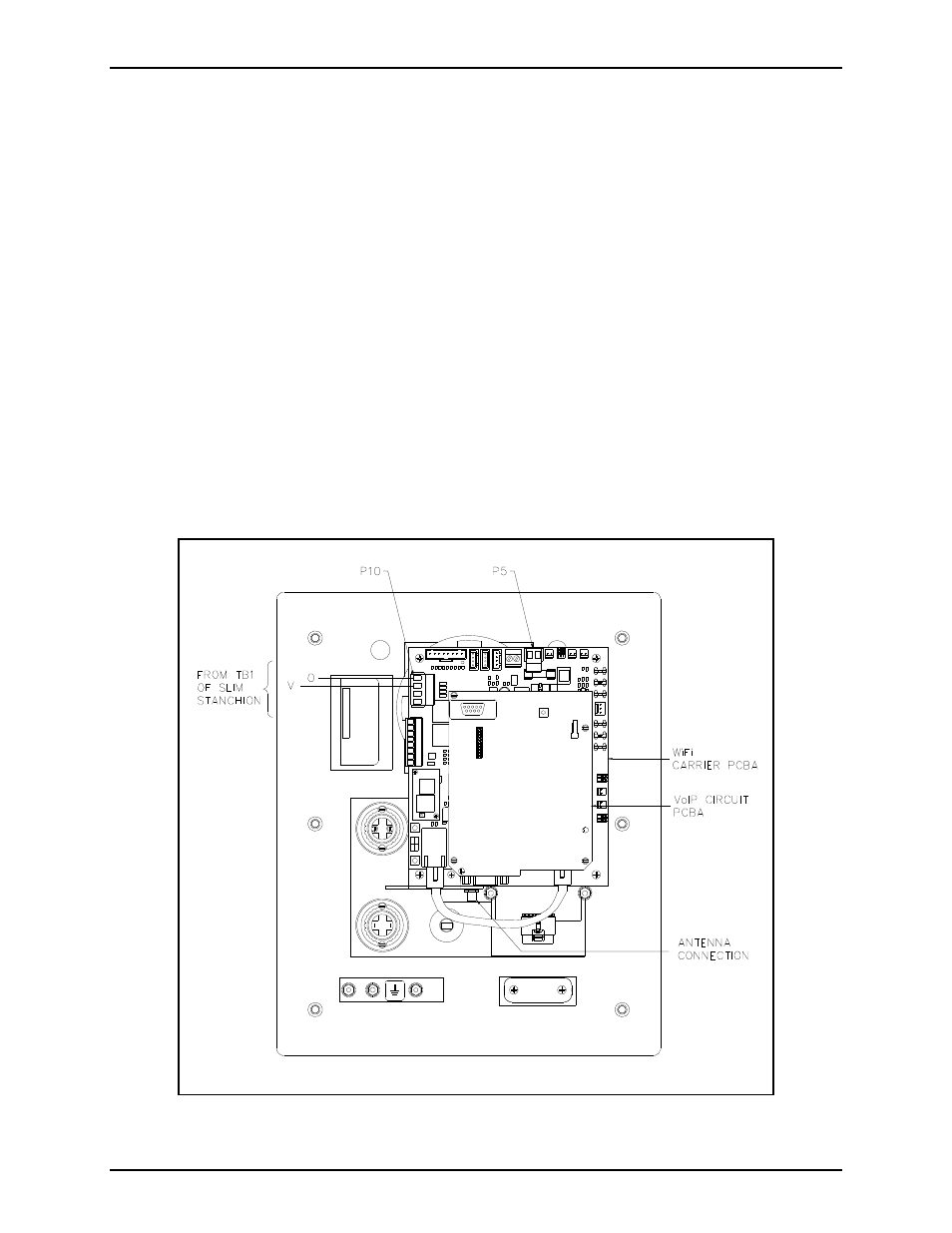
Refer to Figure 5 and Figure 6.
1. The ac power line must enter the stanchion through one of the holes on the left side of the unit when
viewed from the front. Secure the wires to the terminal block as noted on the label.
2. Install the violet (V) and orange (O) beacon wires from inside the stanchion to P10 on the WiFi
Carrier PCBA as shown in Figure 5.
3. Attach the connector from the WiFi antenna wire to the antenna connector mounted on the WiFi
Carrier PCBA.
4. WiFi telephones require a local power source to operate. Each WiFi Telephone includes terminal
block P5 for connection of local power to the telephone. Connect the positive conductor to the (+)
terminal and the negative conductor to the (−) terminal of P5 on the telephone (customer-supplied
wiring). Connect the positive conductor to the (+) terminal (3) and the negative conductor to the (−)
terminal (4) of the TB1 located in the top section of the stanchion. See Figure 5 and Figure 6 for 24
V dc wiring as well as the appropriate telephone installation manuals.
Figure 5.