Power, Power-over-ethernet (poe), Local power – GAI-Tronics 352-701 UL Class 1 Division 1 VoIP Telephones User Manual
Page 9: Network cable, Inputs
Pub. 42004-456C
Model 352-701 and 352-703 Division 1 VoIP Telephones
Page 9 of 20
f:\standard ioms - current release\42004 instr. manuals\42004-456c.doc
02/15
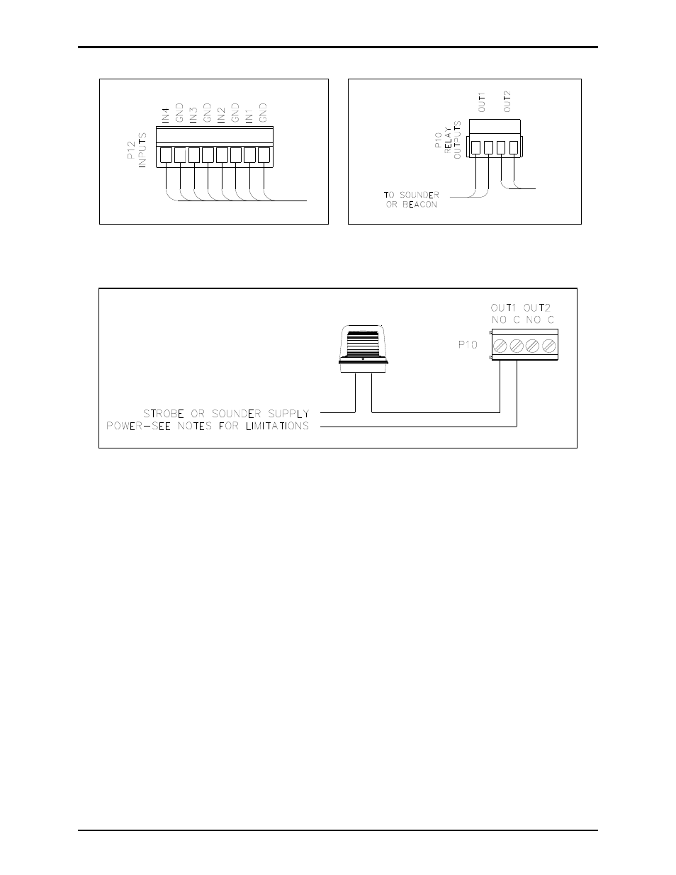
Figure 8. Input Cable Connections at P12
Figure 9. Output Cable Connections at P10
Figure 10.
Power
Power-Over-Ethernet (POE)
Connect power to the system as indicated in your POE equipment manual. (Power Mode A, Class 0)
Local Power
When POE is not available, this telephone can operate from a local 24–48 V dc power source. A
removable terminal block, P5, has been provided for connection of local power to the telephone. Connect
the positive conductor to the (+) terminal and the negative conductor to the (−) terminal of P5.
Connection is polarity sensitive.
Network Cable
Connect a Cat5 or Cat5e UTP cable with an RJ45 connector between the Local Area Network (LAN) and
the VoIP PCBA.
I/O
Inputs
Four auxiliary inputs have been provided for customer use. Terminations for these inputs are provided on
terminal block P12. Connect each input between the desired input (INPUT 1–4) and common (COM) on
terminal block P12. Refer to the “Inputs” section of Pub. 42004-481 for programming instructions of
these inputs.