GAI-Tronics 12584-002 I/O Control Module User Manual
Page 3
Pub. 42004-388B
Model 12584-002 I/O Control Module
Page: 3 of 15
\\s_eng\gtcproddocs\standard ioms - current release\42004 instr. manuals\42004-388b.doc
04/07
Address Switches S1 and S2
S1 an S2 are hexadecimal switches that are used to set the I/O Controller’s address. If the system
contains more than one I/O Controller, each device must be set with a different address. The device’s
addressing should be set in sequential order starting with address 01. Switch S2 sets the first digit and
switch S1 sets the second digit.
Example:
Address 01:
S2 = 0, S1 = 1
Address 02:
S2 = 0, S1 = 2
Address 03:
S2 = 0, S1 = 3
N
OTE
: After changing the board address, the RESET button must be momentarily depressed for the new
address to take effect.
DIP Switch S4
An 8-position DIP switch S4 sets various data parameters and operation parameters of the I/O controller.
The following tables indicate each switch position and the corresponding settings/functions.
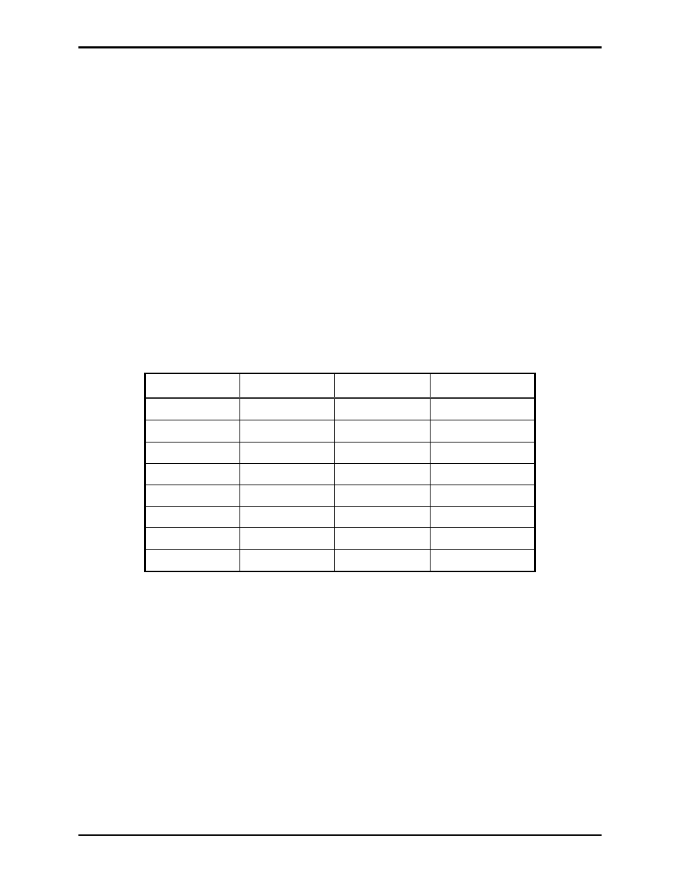
DIP switch S4 positions 1-3 set the serial data line baud rate as follows:
Table 1. DIP Switch S4 Positions 1–3: Baud Rate
Switch S4-1
Switch S4-2
Switch S4-3
Baud Rate
Closed Closed Closed 2400
Open Closed Closed 4800
Closed Open Closed 9600
Open Open Closed 19200
Closed Closed Open 38400
Open Closed Open 57600
Closed Open Open 115200
Open Open Open 115200