GAI-Tronics 10961-001 AMI Centra-Page Interface User Manual
Page 9
Pub. 42004-371B
Model 10961-001 AMI Centra-Page Interface
Page: 9 of 22
\\s_eng\gtcproddocs\standard ioms - current release\42004 instr. manuals\42004-371b.doc
09/05
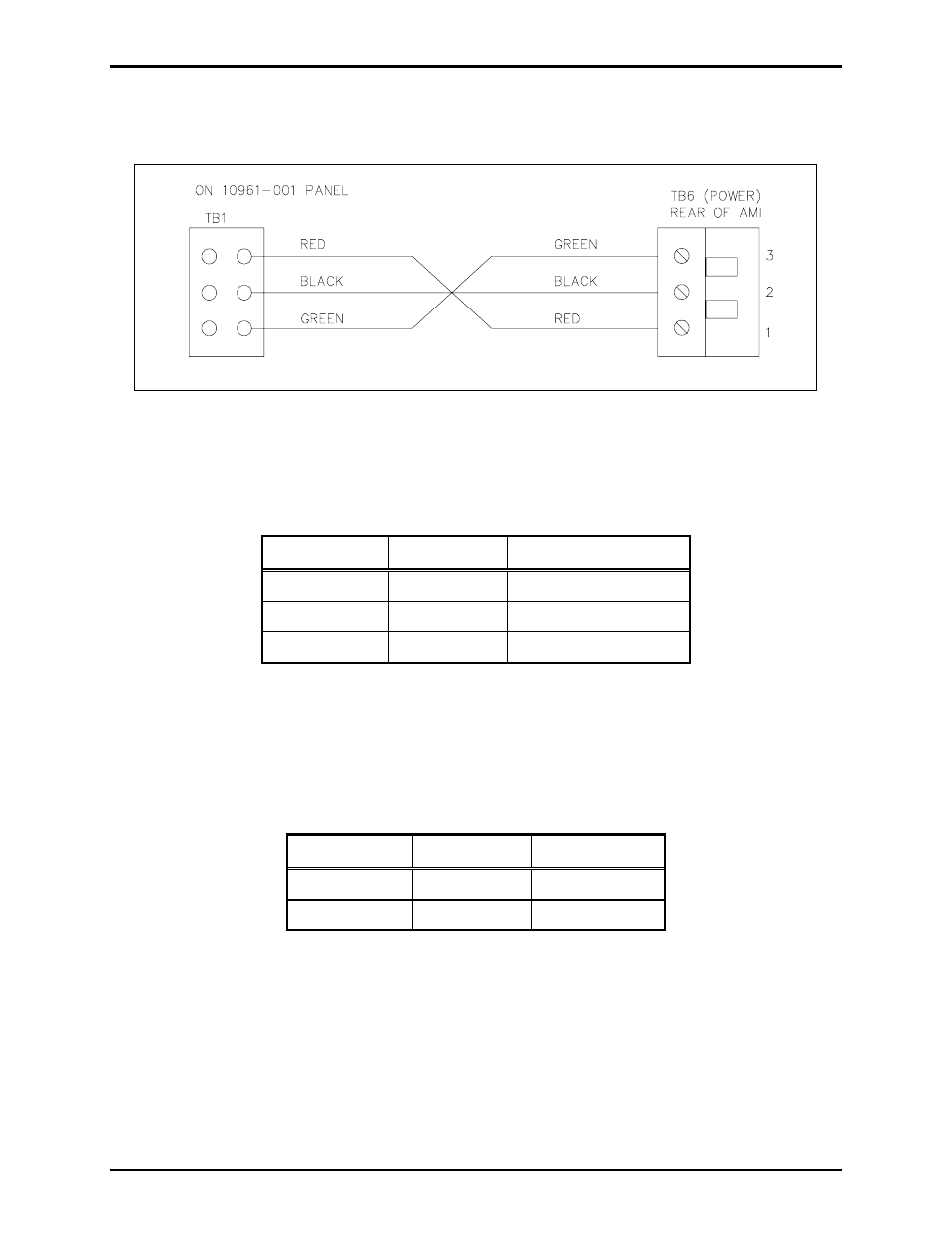
5. Remove TB6 (power) connector plug from its socket on the back of the AMI. Attach the TB6
connector plug to the 61531-040 cable assembly conductor ends that do not have spade lugs. Refer to
Figure 7.
Figure 7. 61531-040 Cable Assembly Connector Termination
6. Connect the 61531-038 and 61531-039 cable assemblies to the outside of TB1 (mounted on the AMI
Centra-Page Interface plate) and the 61531-040 cable assembly to the inside of TB1.
TB1 on AMI Centra-Page Interface Panel
Terminal Wire
Color
Function
TB1-1
Red
+24 V dc
TB1-2
Black
(-) of 24 V dc
TB1-3 Green Ground
7. Connect the 61531-033 cable connector to TB1 on the 69542-001 PCBA.
8. Connect the 61531-034 cable connector (the end without the brown and black wires) to TB3 on the
69542-001 PCBA. Connect the brown and black wires to TB2 on the 69407-002 PCBA.
TB2 on 69542-001
Terminal Wire
Color
Function
TB2-1 Brown +RS485
data
TB2-2 Black -RS485
data
9. Connect the 61531-035 cable connector to TBX04 on the 69542-001 PCBA.