GAI-Tronics 10961-001 AMI Centra-Page Interface User Manual
Page 12
Pub. 42004-371B
Model 10961-001 AMI Centra-Page Interface
Page: 12 of 22
\\s_eng\gtcproddocs\standard ioms - current release\42004 instr. manuals\42004-371b.doc
09/05
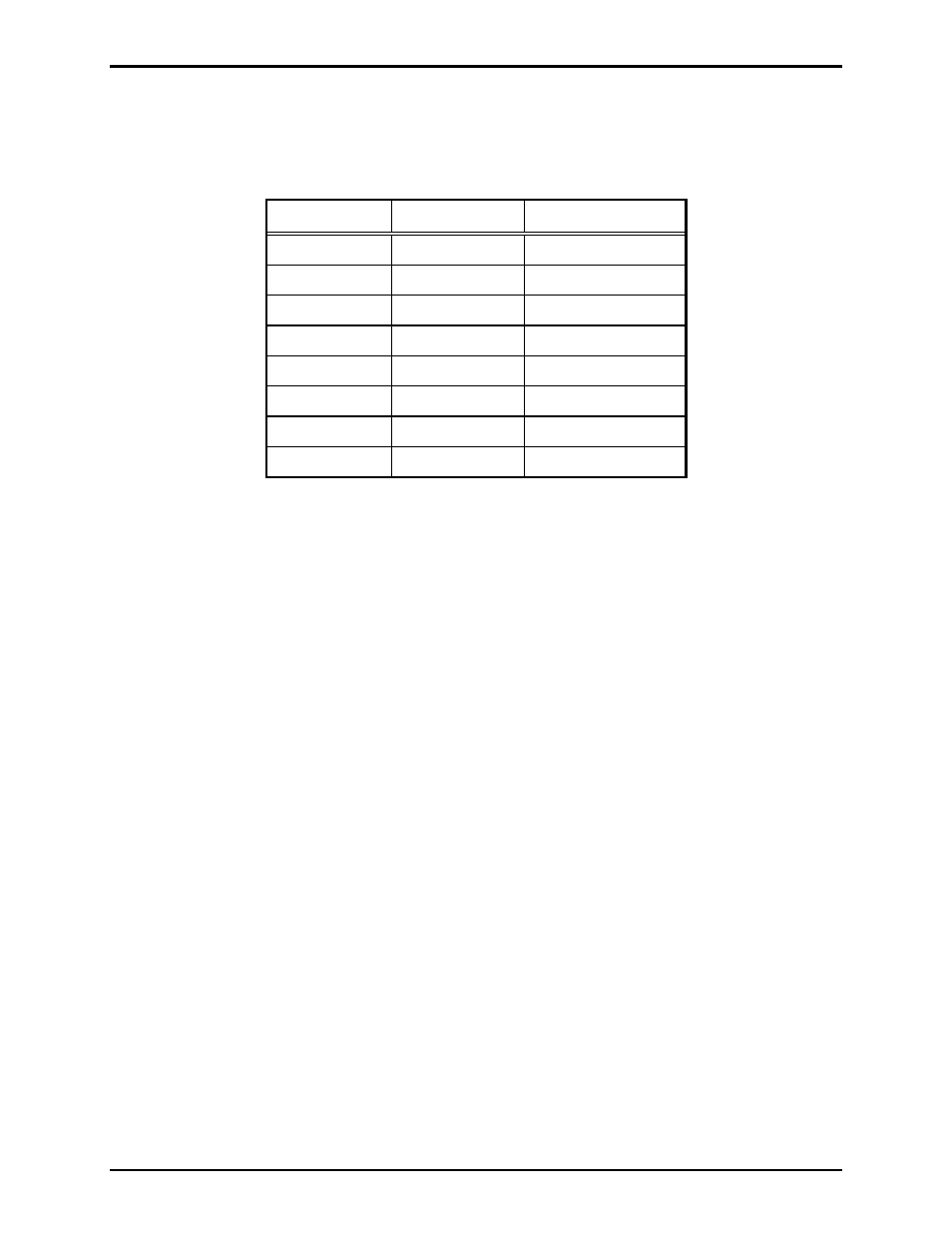
14. Connect the 61531-035 cable assembly to the bottom card rack’s TBX04 according to the table
below, except for the black wire, which goes to the position 2 of the terminal block for the crew’s
quarters.
Card Rack - TBX04
Terminal Wire
Color Function
TBX04-4 Orange Alarm
mute
TBX04-5 Yellow Alarm
TBX04-6 Red/blue Page
TBX04-7 Black/yellow
Alarm
common
TBX04-8 Red
Party
2
TBX04-9 Tan/red Party
common
TBX04-10 Violet
Party
1
TBX04-11 Blue/red Page
common
15. Install the modular RJ11 splitter into the RJ11 jack on the rear on the AMI. Connect the phone cable
from the AMI Centra-Page Interface into one of the splitter RJ11 jacks. Connect the telephone line
into the other splitter RJ11 jack.
16. Remove the SmartMedia
®
card from the AMI and replace it with the SmartMedia
®
card that came
with the AMI Centra-Page Interface. Keep the SmartMedia
®
card as a spare.
N
OTE
: The 12 V dc Walpac is not used in this installation.
17. All field wiring is brought into the terminal blocks on the cabinet back panel. After the field wiring is
connected, apply 24 V dc to TB11 on the central cabinet’s rear panel. Refer to Figure 3.