GAI-Tronics WCB104 Wireless Call-Box Installation Guide User Manual
Page 4
Pub. 42004-327A
Model WCB104 Wireless Call Box Installation Guide
Page: 4 of 10
\\s_eng\gtcproddocs\standard ioms - current release\42004 instr. manuals\42004-327a.doc
12/00
Mounting the Call Box
1. Prior to installation of call box, complete the mounting bracket installation as outlined in GTC Pub.
42003-187 and the pole cap assembly installation as outlined in GTC Pub. 42003-188.
2. Disassemble the call-box assembly by opening the rear section and lifting. To open the rear section,
turn the key and push the button to actuate the lever latch assembly. If necessary, disconnect the
GN/YW ground wire on the left side of the battery bracket. Place the front and middle sections in a
secure area to prevent damage until installation of rear section is complete.
3. Pull the cables and wires through the 1-inch hole drilled previously in the pole and through the
mounting bracket.
4. Pull the cables and wire through the rear section of the call box.
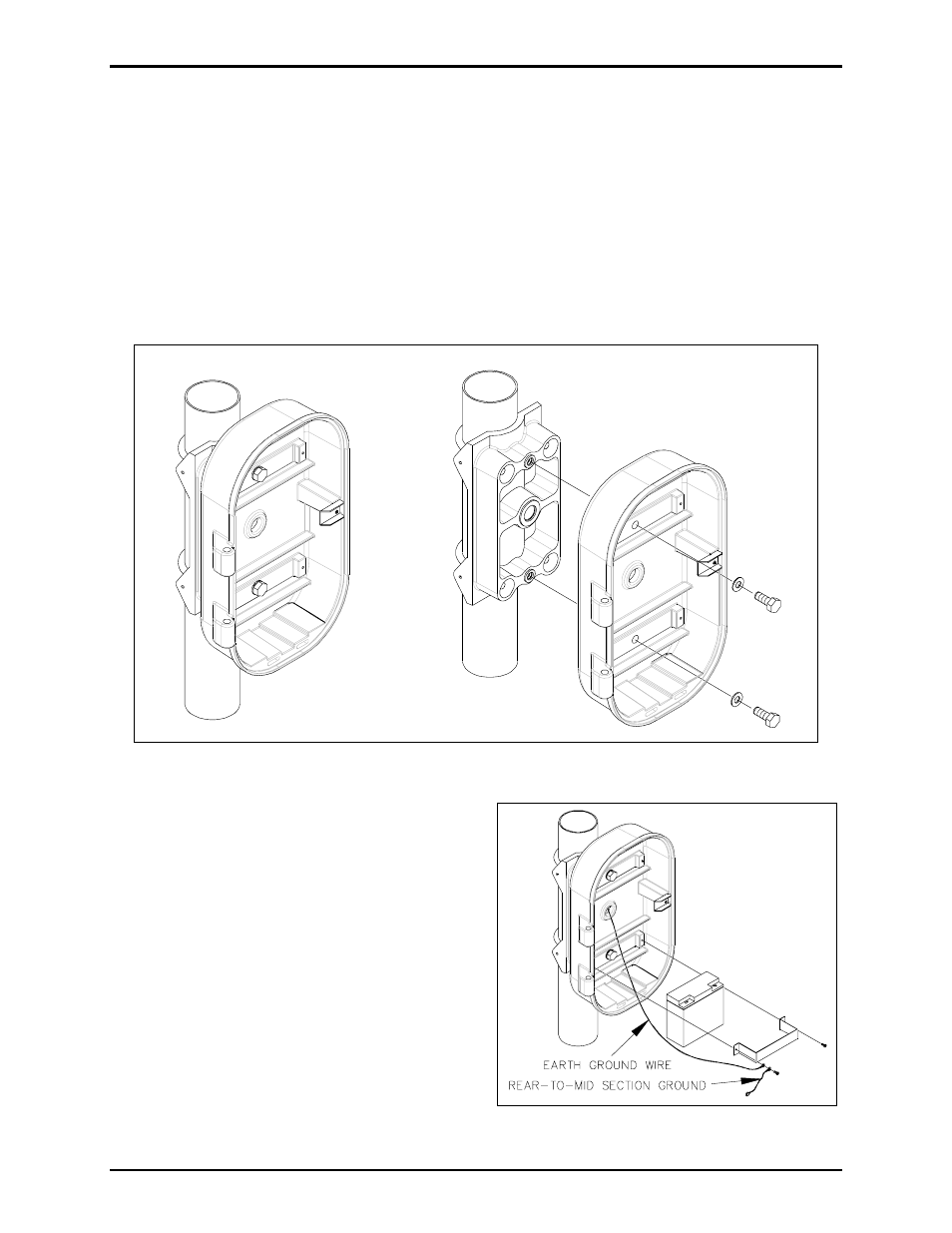
5. Mount the call box rear section using the two
bolts provided to mate the call box to the
mounting bracket holes. Refer to Figure 3 above.
Tighten the bolts to a torque of 20 foot-pounds.
6. Install battery as shown in Figure 4. Install the
earth ground wire and the rear-to-middle ground
wire on the left side of the battery bracket.
7. Install the front and center sections of the call
box by lining up the hinge pins while in the open
position and lowering into place.
Figure 3. Mounting Call Box to Pole Mounting Bracket
Figure 4. Battery Installation