Chapter 2 installation instructions, Fan connectors: cpu_fan, fan_1, fan_2, Audio connectors: cd_in, aux_in – Foxconn NF3250K8AA-ERS User Manual
Page 24: Front audio connector: f_audio, There are three fan connectors on this motherboard
17
Chapter 2 Installation Instructions
NF3250K8AA/NF3250GK8AA Series User Manual
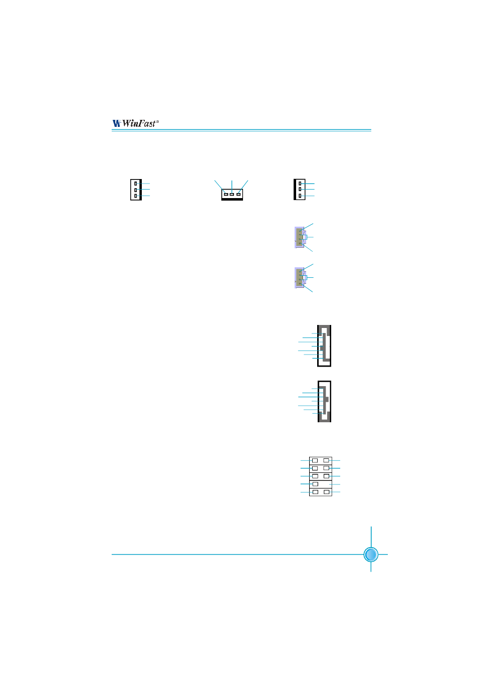
Fan Connectors: CPU_FAN, FAN_1, FAN_2
There are three fan connectors on this motherboard.
Audio Connectors: CD_IN, AUX_IN
CD _IN, A UX _IN is S on y stan dard C D au dio
connectors, to receive audio input from the CD-ROM,
attach its audio connector to the CD_IN/AUX_IN au-
dio connectors on the motherboard.
The Serial ATA connectors are used to connect
the S-ATA devices to the motherboard. These
connectors support the thin Serial ATA cables
for primary internal storage devices. The cur-
rent S-ATA interface allows up to 150MB/s data
transfer rate. SATA_1, SATA_2 are controlled by
NVIDIA chipset, SATA_3, SATA_4 are controlled
by Silicon 3112A (optional).
S-ATA Connectors: SATA_1, SATA_2, SATA_3 (optional), SATA_4
(optional)
The audio port includes two parts – the Front
Audio and Rear Audio. Their priority is se-
quenced from high to low (Front Audio to Rear
Audio). If headphones are plugged into the front
panel of the chassis (using the Front Audio),
then the Line Out (Rear Audio) on the rear panel
will not work. If you do not want to use the Front
Audio, pin 5 and 6, pin 9 and 10 must be short,
and then the signal will be sent to the rear au-
dio port.
Front Audio Connector: F_AUDIO
F_AUDIO
MIC_GND
MIC_IN
+5VAC
MIC_PWR
AUD_RET_R
AUD_OUT_R
EMPTY
AUD_OUT_L
AUD_RET_L
1 2
9 10
NC
GND
GND
GND
TX+
TX-
RX+
RX-
1
SATA_1
SATA_2/SATA_3/SATA_4
GND
GND
GND
RX+
RX-
TX+
TX-
1
FAN_2
CPU_FAN
+12V SENSE
GND
1
FAN_1
SENSE
+12V
GND
1
SENSE
+12V
GND
1
CD_IN
CD_R
GND
CD_L
1
AUX_IN
AUX_R
GND
AUX_L
1