Foxconn NF3250K8AA-ERS User Manual
Page 11
Chapter 1 Product Introduction
4
NF3250K8AA/NF3250GK8AA Series User Manual
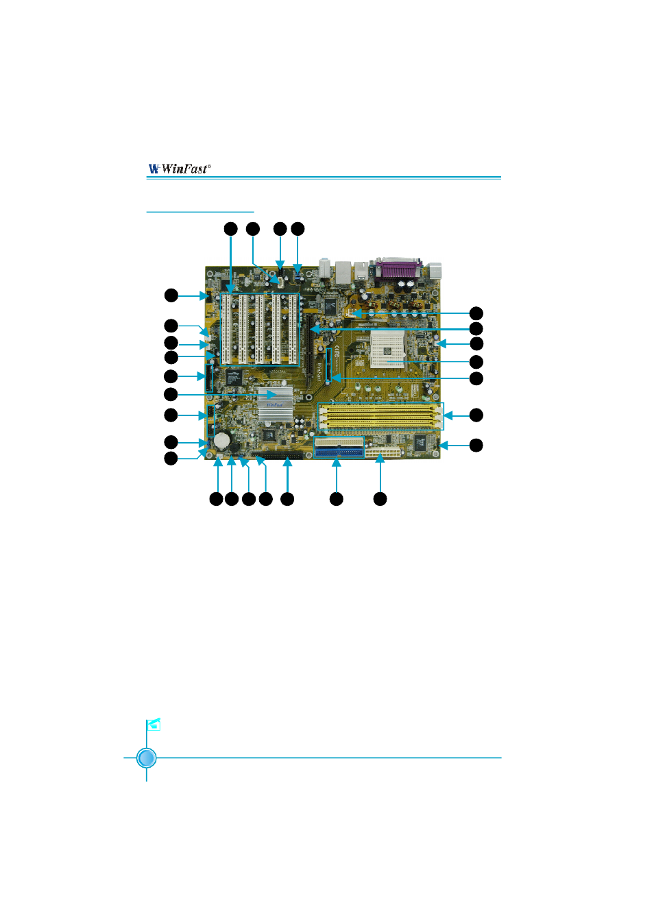
1. Front 1394 Connector (optional)
2. System Fan Connector
3. Wake Up On Modem Connector
4. S/PDIF Out Connector
5. SATA Connectors (controlled by
NVIDIA Chipset )
6. NVIDIA nForce3 250/nForce3 250Gb
7. Front USB Connectors
8. Clear CMOS Jumper
9. Chassis Intruder Connector
10. Chipset Fan Connector
11. Speaker Connector
12. BIOS TBL Jumper
13. Front Panel Connector
14. Floppy Disk Connector
15. IDE Connectors
16. ATX Power Connector
17. IrDA Connector
18. DDR DIMM Slots
19. SATA connectors (controlled by
Silicon 3112A) (optional)
20.CPU Socket
21. CPU Fan Connector
22. AGP Slot
23. 12V ATX Power Connector
24. Front Audio Connector
25. CD_IN Connector
26. AUX_IN Connector
27. PCI Expansion slots
Motherboard Layout
Note:The above motherboard layout is provided for reference
only; please refer to the physical motherboard.
1
2
3
4
5
6
14
13
12
11
10
9
8
7
15
16
17
18
19
20
21
22
24
25
26
27
23