Chapter 2 installation instructions, Usb connectors: f_usb 1, f_usb 2, Irda connector: ir – Foxconn NF3250K8AA-ERS User Manual
Page 23
16
Chapter 2 Installation Instructions
NF3250K8AA/NF3250GK8AA Series User Manual
Hard Disk LED Connector (IDE_LED)
Attach the connector to the IDE_LED on the front panel of the case; the LED will
flash while the HDD is in operation.
Reset Switch (RESET)
Attach the connector to the Reset switch on the front panel of the case; the
system will restart when the switch is pressed.
Power LED Connector (PLED)
Attach the connector to the Power LED on the front panel of the case. The Power
LED indicates the power supply status. When the system is in S0 status, the
LED is on. When the system is in S1 status, the LED is blink. When the system
is in S3, S4, S5 status, the LED is off.
Power Switch Connector (PWRBTN#)
Attach the connector to the power button of the case. Pushing this switch allows
the system to be turned on and off rather than using the power supply button.
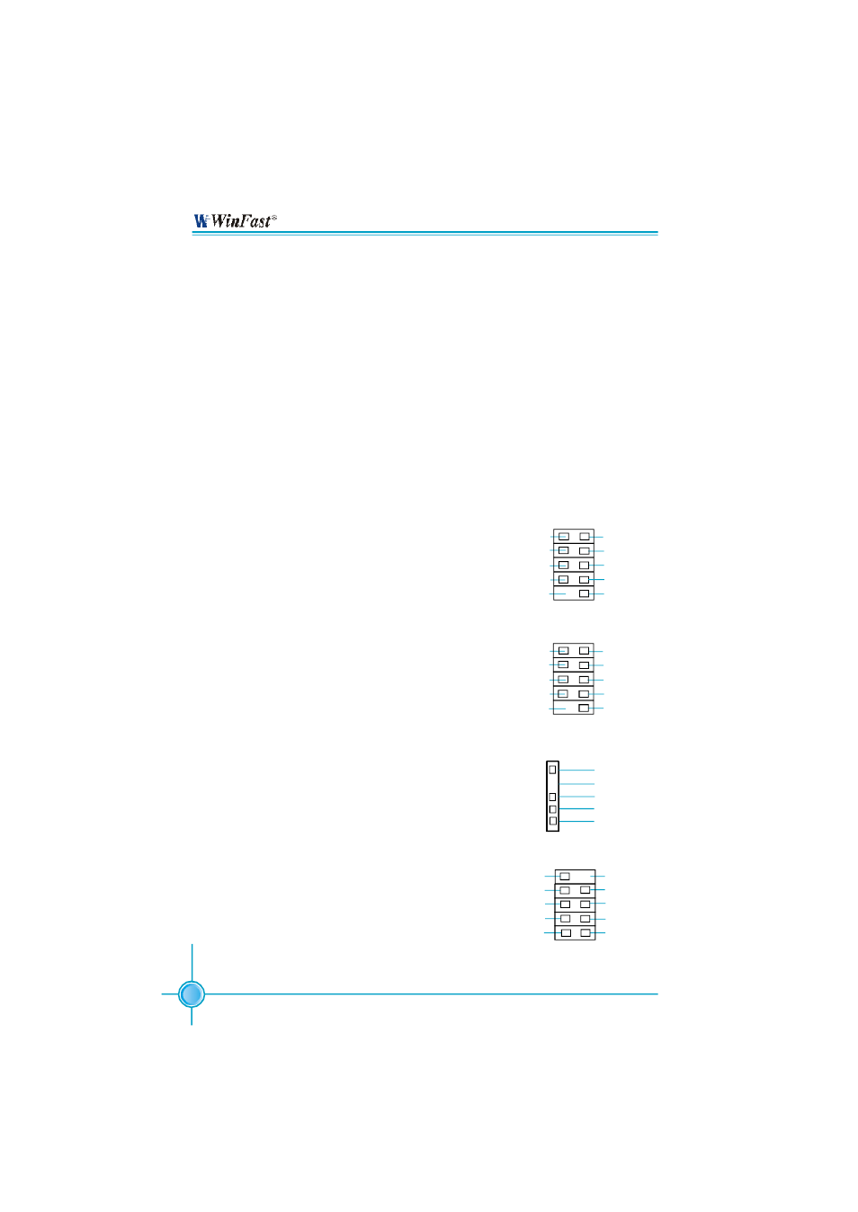
USB Connectors: F_USB 1, F_USB 2
Besides four USB ports on the rear panel, the series
of motherboards also have two 10-pin headers on
board which may connect to the front panel USB
cable to provide additional four USB ports.
IrDA Connector: IR
The IrDA infrared transmission allows your com-
puter to send and receive data via an infrared ray.
The relevant parameters for the BIOS Integrated
Peripherals should be set prior to using this
function.
IR
+5V
GND
IRRX
IRTX
Empty
1
F_USB1
D5-
VCC
D4+
D4-
Empty
GND
NC
VCC
GND
D5+
1 2
9 10
1394 Connector(optional): F_1394
The 1394 expansion cable can be connected to ei-
ther the front (provided that the front panel of your
chassis is equipped with the appropriate interface)
or the rear panel of the chassis.
F_USB2
D7-
VCC
D6+
D6-
Empty
GND
NC
VCC
GND
D7+
1 2
9 10
Empty
10
9
F_1394
TPB+
TPA+
+12V
GND
TPB-
+12V
GND
GND
TPA-
2
1