Figure 9), Figure 8, Figure 8) – Flowserve Logix 1200e LGAIM0044 User Manual
Page 9
Flowserve Corporation, Valtek Control Products, Tel. USA 801 489 8611
44-9
9. Remove the tubing from the orifice in the driver
module assembly (Figure 9).
10.Remove the two wiring connections that link the
driver module assembly to the collector board.
11.Feed the wires back through the housing so they
extend backward, out toward the driver module
opening. This will allow the driver module to thread
out without tangling or cutting the wires.
12.Grasp the driver module pressure modulator cap to
rotate the entire driver module. Turn it counter
clockwise to remove. After it is threaded out, care-
fully retract the driver module from the housing.
13.Take new driver module, and verify that the O-ring
is in place. Lay the wires back and along modulator
as shown in Figure 7, and hold in place by hand.
14.Gently direct the driver module into the housing
bore. Turn the driver module clockwise to thread it
into the housing. Continue rotating the module until
it bottoms out.
15.Once the threads are fully engaged, rotate the
driver module counter clockwise until the flat on the
driver module and the flat on the housing are
aligned. This will align the screw holes for the next
step.
16.Verify that nylon gasket is in the counter bore in the
driver module retaining screw hole as shown in
Figure 8.
17.Insert a driver-to-housing screw into the driver
housing through the counter-bored hole in posi-
tioner main housing. Tighten with a phillips screw-
driver.
18.Feed the driver module wires into the main cham-
ber of the housing, and connect them to the collec-
tor board.
19.Verify that the three O-rings are in the counter-
bores on the machined platform where the spool
valve block is to be placed (Figure 20).
20.Carefully slide the spool into the connecting clip of
the driver module assembly.
21.Carefully slide the block over the spool, using the
machined surface of the housing base as a register
(Figure 8). Slide the block toward the driver module
until the two retaining holes line up with the
threaded holes in the base.
22.Install two spool-valve screws and tighten securely
with a Phillips screwdriver.
23.Slide the spool valve cover assembly over the spool
valve until the tang engages into housing slot.
Install spool valve cover screw and tighten securely.
24.Thread main cover and driver module cover into
the main housing.
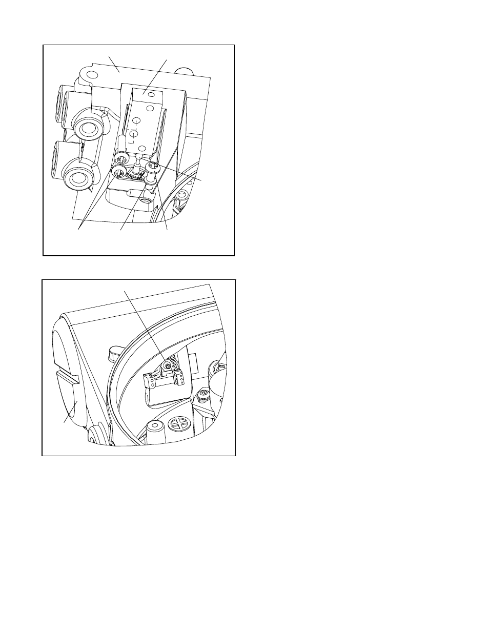
Figure 8: Spool and Block
Figure 9: Driver Module Orifice
Spool Valve
Screws
N
y lon
Gaskets
Driver to
Housing Screws
Spool
Spool Valve Block
Housing
D
river
M
odul e
Cover
Orifice