Spool valve, Regulator, Replacing regulator – Flowserve Logix 1200e LGAIM0044 User Manual
Page 10: Spool valve cover, Replacing filter in spool valve cover
44-10
Flowserve Corporation, Valtek Control Products, Tel. USA 801 489 8611
Spool Valve
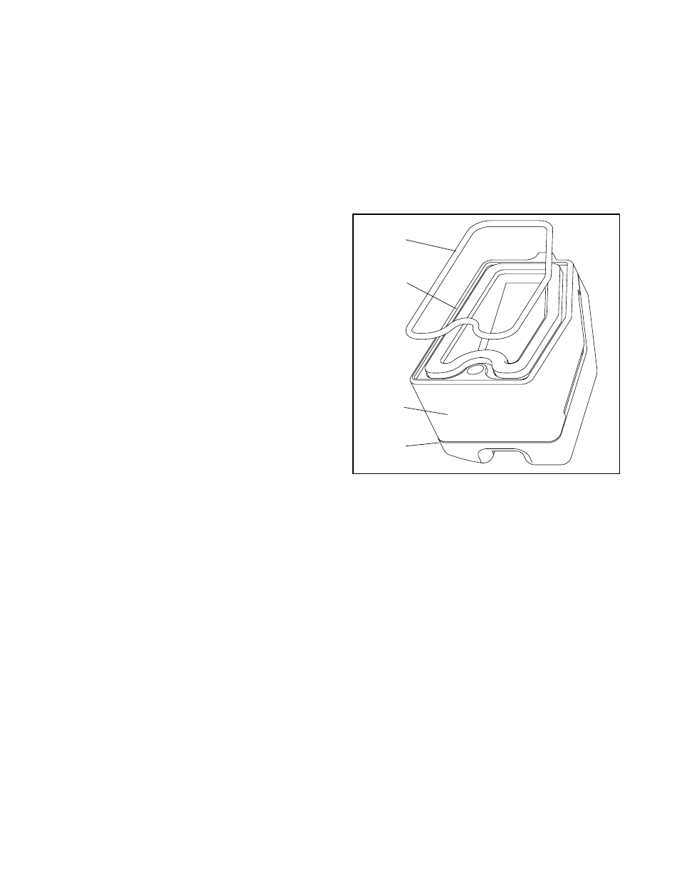
To replace the spool valve, refer to Figure 8, 10 & 11
and proceed as outlined below.
1. Make sure valve is bypassed or in a safe condition.
2. Disconnect the power and air supply to the unit.
3. Remove the spool valve cover by removing the
screw and sliding the cover assembly backwards
until the tab is clear of the slot. It is not necessary
to remove the sheet metal cap, hydrophobic filter,
or O-ring from this assembly (Figure 11).
4. Remove the spool valve block by removing the two
phillips-head screws and carefully sliding the block
off the spool (Figure 8).
CAUTION: Spool (extending from driver assem-
bly) is easily damaged. Use extreme caution
when handling spool and spool valve block.
5. Carefully remove spool by sliding end of spool out
of connecting clip. Excessive force may bend the
spool.
6. Verify that the three O-rings are in the counter-
bores on the machined platform where the new
spool valve block is to be placed (Figure 20).
7. Careful slide the spool into the connecting clip of
the driver module assembly.
8. Carefully slide the block over the spool, using the
machined surface of the housing base as a register
(Figure 8). Slide the block toward the driver module
until the two retaining holes line up with the
threaded holes in the base.
9. Install two spool-valve screws and tighten securely
with a phillips screwdriver.
10.Slide the spool valve cover assembly over the spool
valve until the tang engages into housing slot.
Install the spool valve cover screw and tighten
securely.
Regulator
The regulator reduces the pressure of the incoming
supply air to a level that the driver module can use.
Replacing Regulator
1. Make sure valve is bypassed or in a safe condition.
2. Disconnect the power and air supply to the unit.
3. Remove the main cover.
4. Remove the four wire connections from the collec-
tor board. Next remove the four screws that fasten
the collector board to the housing.
5. Grasp the bottom of the regulator and unscrew it
from the interface plate.
6. Verify that the O-rings are in place on the base of
the new regulator and thread it into the hole in
interface plate.
7. Install four screws to fasten the collector board into
the housing. Replace the four wire connections.
8. Attach the flexible tubing to the orifice.
9. Re-install all covers.
Spool Valve Cover
The spool valve cover incorporates a coalescing filter
element in a two-piece cover. This protects the spool
valve chamber from moisture and provides a low back
pressure vent for exhaust air from the spool valve.
Replacing Filter in Spool Valve Cover
1. Make sure valve is bypassed or in a safe condition.
2. Disconnect the power and air supply to the unit.
3. Remove the spool cover by removing the screw
and sliding the cover assembly backwards until the
tab is clear of the slot. The sheet metal cover may
be removed and cleaned with a brush or by blowing
out with compressed air (Figure 11).
4. Remove the O-ring from around hydrophobic filter
element and set aside (Figure 10).
5. Remove the molded filter element by pulling
straight out of chamber cover vent piece.
6. Install O-ring into base of chamber cover vent piece
as shown in Figure 10.
Figure 10: Spool Valve Cover Assembly
O-ring
H
yd rophobic
Filter
Spool
Valve
Cover
Spool
Valve Shroud