Unpacking, Logix 1200e positioner overview, Specifications – Flowserve Logix 1200e LGAIM0044 User Manual
Page 3
Flowserve Corporation, Valtek Control Products, Tel. USA 801 489 8611
44-3
Unpacking
1. While unpacking the Logix 1200e positioner, check
the packing list against the materials received. Lists
describing the system and accessories are
included in each shipping container.
2. When lifting the system from the shipping con-
tainer, position lifting straps to avoid damage to
mounted accessories. Systems with valves up to
six inches may be lifted by actuator lifting ring. On
larger systems, lift unit using lifting straps or hooks
through the yoke legs and outer end of body.
WARNING: When lifting a valve/actuator assem-
bly with lifting straps, be aware the center of
gravity may be above the lifting point. There-
fore, support must be given to prevent the
valve/actuator from rotating. Failure to do so
can cause serious injury to personnel or dam-
age to nearby equipment.
3. In the event of shipping damage, contact the ship-
per immediately.
4. Should any problem arise, contact a Flowserve
Flow Control Division representative.
Logix 1200e Positioner Overview
The Logix 1200e digital positioner is a two-wire,
4-20 mA input, digital valve positioner. The Logix
1200e positioner also utilizes the HART protocol to
allow two-way remote communications with the posi-
tioner. The Logix 1200e positioner can control both
double and single-acting actuators with linear and
rotary mountings. Start up current must be at least
3.5 mA but once started, the Logix 1200e digital posi-
tioner operates with a signal as low as 2.8 mA. Below
2.8 mA, the operation and communication are sus-
pended.
Since the positioner is insensitive to supply pressure
changes and can handle supply pressures from 30 to
150 psig, a supply regulator is usually not required;
however, in applications where the supply pressure is
higher than the maximum actuator pressure rating a
supply regulator is required to lower the pressure to
the actuator’s maximum rating (not to be confused
with operating range). An air filter is required for all
applications due to the close clearances in the spool.
NOTE: The air supply must conform to ISA Standard
ISA 7.0.01 (a dew point at least 18 degrees Fahrenheit
below ambient temperature, particle size below five
microns – one micron recommended – and oil content
not to exceed one part per million).
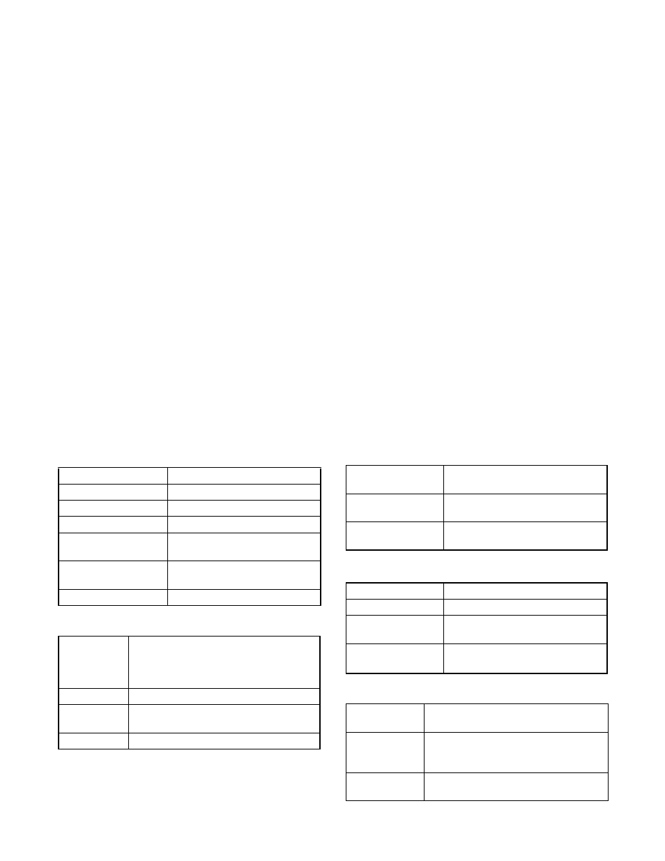
Specifications
Table I: Electrical Specifications
Power supply
Two-wire, 4-20 mA 12.0 VDC
Compliance voltage
12.0 VDC
Effective resistance
625
Ω
@ 20 mA
Communications
HART Protocol
Minimum required
start-up current
3.5 mA
Minimum operating
current
2.8 mA
Maximum voltage
40.0 VDC
Table II: SoftTools Suite Software Specifications
Computer
Minimum Pentium processor running Win-
dows 95 or NT, 16-MB total memory
(32-MB recommended), 20-MB available
hard disk space, one CD-ROM drive
HART Modem RS-232 Modem or PCMCIA card
HART Filter
May be required in conjunction with some
DCSs
HART MUX
MTL 4840 system
Table III: Physical Specifications
Operating
Temperature Range
-40° F to +185° F
(-40° C to +85° C)
Housing
Cast, powder-painted aluminum,
stainless steel
Weight
8.3 pounds (3.9 kg) aluminum 20.5
pounds (9.3 kg) stainless steel
Table IV: Positioner Specifications
Dead band
<0.1% full scale
Repeatability
< 0.05% full scale
Linearity
< 0.5% (rotary), < 0.8%
(sliding stem) full scale
Air Consumption at
< 0.3 SCFM (0.5 Nm
3
/hr)@60 psig
(4 barg)
Table V: Hazardous Area Certifications
Explosion Proof
FM/CSA Class 1, Div 1, Groups B, C, D
CENELEC EExd IIB+H2 T5, IP-66
Non-incendive
FM/CSA Class 1, Div 2, Groups A, B, C,
D; CENELEC IIC Exn, T6,BS 6941,
IP-66, T
Intrinsically Safe
FM/CSA Class 1, Div 1, Groups A, B, C,
D; CENELEC EExib, T4 & T5, IP-66