Figure 19: driver module minimum pressure check – Flowserve Logix 1200e LGAIM0044 User Manual
Page 19
Flowserve Corporation, Valtek Control Products, Tel. USA 801 489 8611
44-19
Checking or Setting the Driver Module Minimum
Pressure
Refer to Figure 19, proceed as follows:
1. Make sure valve is bypassed or in a safe condition.
2. Disconnect power from the positioner.
3. Remove the main cover and remove the
1
/
16
flexi-
ble tubing from the orifice.
4. Obtain a No. 10-32 x swivel elbow (Pneumadyne
part No. SFL-10 or equivalent) and a No. 10-32
extension (Clippard part No. 15010 or equivalent).
5. Remove the No. 10-32 x 0.016 orifice and gasket
(Figure 9) from the driver module using a
1
/
2-inch
nut driver. Take care to not misplace the gasket.
6. Screw in the 10-32 extension followed by the 10-32
x swivel elbow.
7. Direct the swivel elbow so the minimum pressure
test port is accessible.
8. Screw a No. 10-32 x
1
/
16
-inch barb fitting into the
test port, and screw the No. 10-32 x 0.016 orifice
into the end of the elbow as shown.
9. Connect the tubing from the internal regulator out-
put port to the orifice.
10.Using some
1
/
16
-inch flexible tubing, connect a 0 to
30 psi gauge to the minimum pressure set port.
11.Once the gauge is connected, reapply the posi-
tioner air supply. The minimum pressure should
now be registering on the gauge and must be 3.8 to
4.2 psi. If the minimum pressure is not correct, take
a
9
/
64
allen wrench and turn the minimum pressure
set screw located at the bottom of the driver mod-
ule (Figure 7) until the pressure is in the range indi-
cated. Cycle the positioner air supply several times
and recheck the minimum pressure and re-adjust, if
necessary, to ensure that the pressure has settled
within the range specified.
12.When the pressure is set, remove the air supply.
13.Remove the No. 10-32 x
1
/
16
barb and orifice from
the swivel elbow and then remove swivel elbow and
extension.
14.Replace the orifice and gasket as shown in
Figure 9 and reconnect the
1
/
16
inch flexible tubing
from the internal regulator output port to the orifice.
Reconnect the positioner air supply and power. The
positioner should now be ready to calibrate.
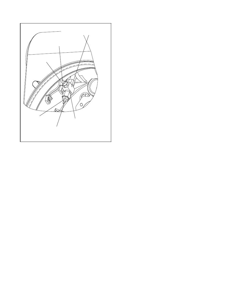
Figure 19: Driver Module Minimum
Pressure Check
Minimum Pressure
Test Port
No.10-32 x
1
/
16
B
a rb
No.10-32 x Swivel
TE
E (Pneumadyne
Part No. SFL-10)
No.10-32 x .016
Orifice
Pressure from Internal
Regulator to be tubed to
this orifice
No. 10-32 Extension
(Clippard Part No. 15010)