Standard rotary mounting procedure (see figure15), Orienting the take-off arm for final lock down, Figure 14: linear mark one control valve mounting – Flowserve Logix 1200e LGAIM0044 User Manual
Page 14
44-14
Flowserve Corporation, Valtek Control Products, Tel. USA 801 489 8611
Standard Rotary Mounting Procedure
(See Figure 15)
The standard rotary mounting applies to valve/actua-
tor assemblies that do not have mounted volume tanks
or handwheels. The standard mounting uses a linkage
directly coupled to the valve shaft. This linkage has
been designed to allow for minimal misalignment
between the positioner and the actuator. The tools
required for the following procedure are:
5
/
32
allen wrench
1
/
2
-inch end wrench
7
/
16
-inch end wrench
3
/
8
-inch socket with extension
3
/
16
nutdriver
1. Fasten spline lever adapter to splined lever using
two No. 6 x 0.50-inch self tapping screws.
2. Slide take-off arm assembly onto spline lever
adapter shaft. Insert screw with star washer
through take-off arm and add second star washer
and nut. Tighten nut with socket so arm is lightly
snug on shaft but still able to rotate. This will be
tightened after linkage is correctly oriented.
3. Attach follower arm to positioner feedback shaft
using the star washer and No. 10-32 nut.
NOTE: Arm will point up when feedback shaft is in
the free position.
1. Using four 0.25-20 x 0.50 L. bolts, fasten positioner
to universal bracket using appropriate hole pattern
(stamped on bracket).
2. Using a
1
/
2
-inch end wrench and two 0.3125
-
18 x
0.50 L. bolts, attach bracket to actuator transfer
case pad. Leave these bolts slightly loose until final
adjustments are made.
3. Rotate take-off arm so the follower pin will slide into
its slot. Adjust bracket position noting the engage-
ment of the follower pin and the take-off arm slot.
The pin should extend approximately
1
/
16-inch
past
take-off arm. When properly adjusted, securely
tighten the bracketing bolts.
Orienting the Take-off Arm for Final Lock Down
Tube positioner to valve in the following manner:
1. OUTPUT 1 port of the manifold to the bottom side
of the Actuator.
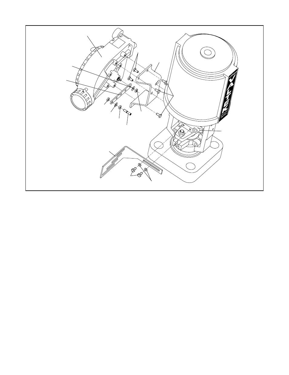
Figure 14: Linear Mark One Control Valve Mounting
Logix 1200 Positioner
Positioner
Bolts
Nut
Lock Washer
Nut
Follower Pin
Take-off Arm
Bolts
Stem Clamp
Bracket Bolts
Bracket
Locknut
Washer
Follower
Arm
Nut
Metal
Washers