Main pcb assembly, Replacing main pcb assembly (figure12), Figure 11 – Flowserve Logix 1200e LGAIM0044 User Manual
Page 11: Figure 11), Figure 11: spool valve cover assembly, Figure 12: main pcb assembly
Flowserve Corporation, Valtek Control Products, Tel. USA 801 489 8611
44-11
7. Place new molded filter element into the chamber
cover vent piece. This element provides part of the
track to secure the O-ring installed in the last step.
8. Place spool valve shroud onto spool valve cover.
9. Place the spool valve cover assembly in place by
setting it on the ramp and sliding it until the tab seats
in the slot (Figure 11) and secure with No. 8-32
screw.
Main PCB Assembly
The main PCB assembly contains the circuit board
and processor that perform control functions of the
positioner. The board is encapsulated in a tray with a
protective silicon coating. This module can be easily
replaced if necessary. None of the components inside
the tray are serviceable. This module is to be replaced
as a unit.
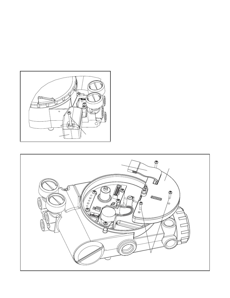
Replacing Main PCB Assembly (Figure 12)
1. Make sure valve is bypassed or in a safe condition.
2. Disconnect the power and air supply to the unit.
3. Remove the main cover and disconnect the ribbon
cable from the collector board.
CAUTION: To avoid damaging any components,
exercise caution by gently raising the locking
tab to release the ribbon cable.
4. Remove the PCB assembly by removing the three
No. 6-32 screws and lifting the tray out of housing.
5. Place the new PCB assembly on the bosses inside
the positioner housing.
6. Insert three No. 6-32 screws through the tray into
the threaded bosses and tighten evenly, using a
phillips screwdriver. Do not overtighten.
7. Reconnect the ribbon cable to the collector board
Figure 11: Spool Valve Cover Assembly
Figure 12: Main PCB Assembly
Ribbon Cable
Screws (3)
Main PCB
Assembly
Screw
Spool Valve Cover