Optional rotary mounting procedure, Figure 16: optional rotary mounting – Flowserve Logix 1200e LGAIM0044 User Manual
Page 16
44-16
Flowserve Corporation, Valtek Control Products, Tel. USA 801 489 8611
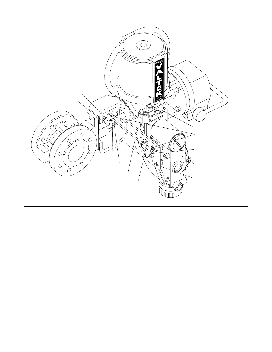
Optional Rotary Mounting Procedure
The optional rotary mounting applies to valve/actuator
assemblies that are equipped with mounted volume
tanks or handwheels. The optional mounting uses a
four-bar linkage coupled to the valve shaft. The follow-
ing tools are required:
3
/
8-inch
box wrench
7
/
16-inch
box wrench
1
/
2-inch
box wrench
1. Using a
1
/
2-inch
box end wrench and two 0.3125
-
18
x 0.50 L. bolts, attach bracket to actuator transfer
case pads. Leave bracket loose to allow for
adjustment.
2. Using four 0.25
-
20 x 0.50 L. bolts and a
7
/
16-inch
box wrench, fasten positioner to universal bracket,
using the four-hole pattern that locates the posi-
tioner the farthest from the valve. Rotate positioner
90 degrees from normal so gauges are facing
upward.
3. Attach follower arm to positioner feedback shaft,
using the star washer and No. 10-32 nut.
4. Attach tripper and tripper clamp to shaft, using two
0.25
-
20 L. bolts and two 0.25
-
20 locknuts. Leave
tripper loose on shaft until final adjustment.
5. Thread ball joint linkage end to tripper and tighten
(Thread locking compound such as Loctite is rec-
ommended to prevent back threading). Adjust
length of tie rod so follower arm and tripper rotate
parallel to each other (the rod must be cut to the
desired length). Connect other ball joint end to fol-
lower arm using a star washer and a No. 10-32 nut.
6. Tighten bracket and tripper bolting.
7. Check for proper operation, note direction of rotation.
Figure 16: Optional Rotary Mounting
Tripper
Tripper Clamp
B
o lts (2)
Locknuts (2)
*Tie Rod
Nut No. 10-32
Lock Washer
Bracket B
o lts
5
/
16
-18 (2)
Ball oint
Ends
Follower Arm
Rotate Positioner 90
°
Mounting B
o lts
1
/
4
-20 (4)
Tie Rod must be cut to desired length