8 basic operation, 9 hart, 10 position definition – Flowserve 500+ Series Logix User Manual
Page 5: 11 command input and final command, 12 outer loop, Asic, Peration, Hart, Osition, Efinition
User Instructions - Logix® 500+ Series Digital Positioners FCD LGENIM0105-10 11/13
flowserve.com
5
PRINCIPLES OF OPERATION
1.8
Basic Operation
The Logix 500+ digital positioner is a two-wire 4-20 mA input
digital valve positioner which uses the HART protocol to
allow two-way remote communications. The positioner is
completely powered by the 4-20 mA input signal. Start-up
current must be at least 3.8 mA. The positioner is
configurable through the local user interface, hand-held or
DTM. The Logix 500+ positioner can control both double-
and single-acting pneumatic actuators with linear or rotary
mountings.
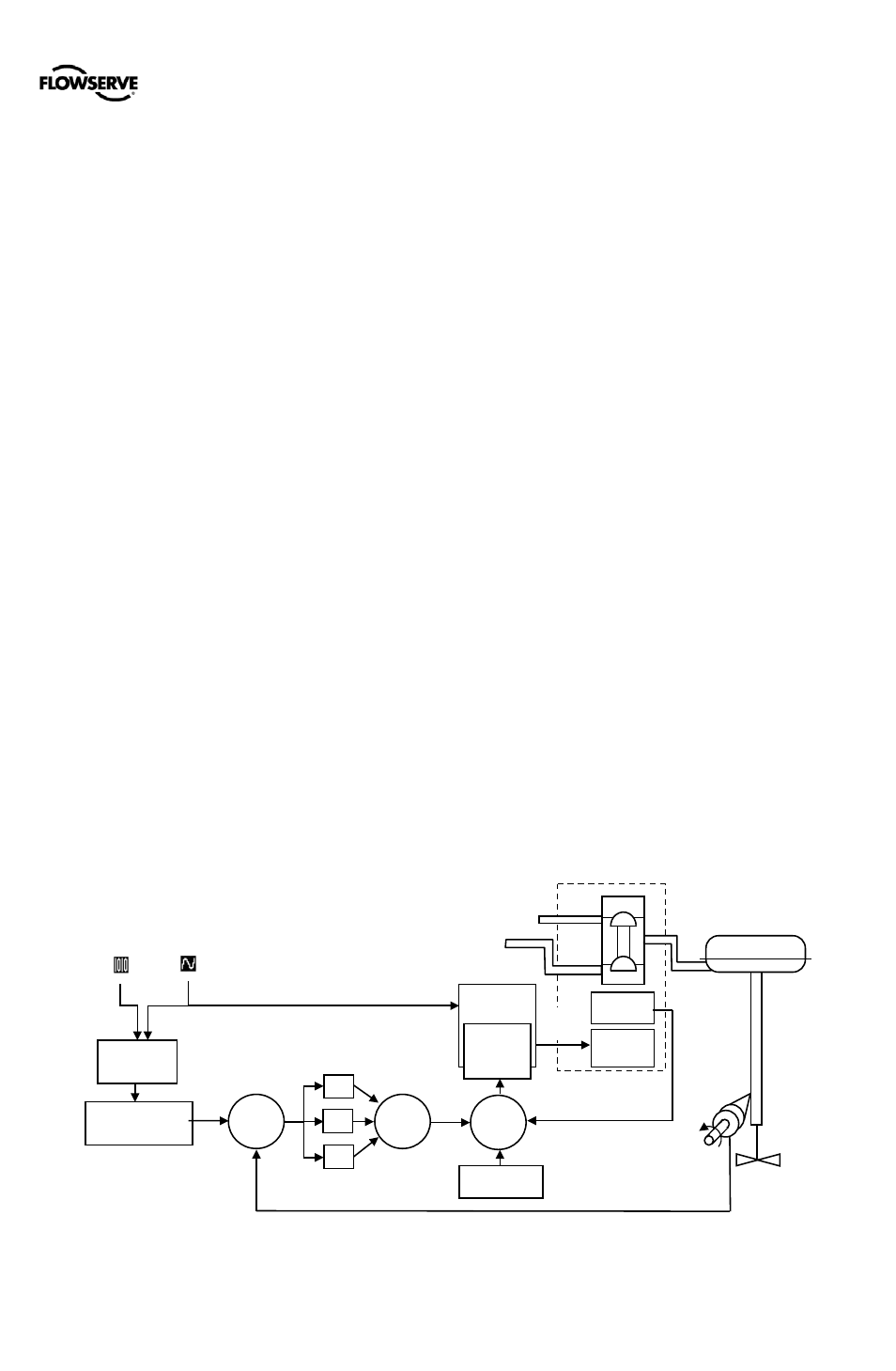
The Logix 500+ digital positioner is an electronic and
pneumatic closed-loop feedback instrument. Figure 1 shows
a schematic of a Logix 500+ positioner installed on a single-
acting linear actuator for air-to-open action. Figure 2 shows
the feedback algorithm.
1.9
HART
The Logix 500+ receives power from the two-wire, 4-20 mA
input signal. However, since this positioner utilizes HART
communications, two sources can be used for the command
signal: Analog and Digital. In Analog source, the 4-20 mA
signal is used for the command source. In Digital source, the
level of the input 4-20 mA signal is ignored (used only for
power) and a digital signal, sent via the HART
communication protocol, is used as the command source.
The command source can be accessed with ValveSight
software, the HART 375 communicator, or other host
software. See section 11 HART COMMUNICATION for more
information.
1.10 Position Definition
Whether in Analog or Digital Source, The position at 0% is
always defined as the valve in a closed position and 100% is
always defined as the valve in an open position. In Analog
Source, the 4-20 mA signal is converted to a position (in
percent). During loop calibration, the signals corresponding
to 0% and 100% are defined.
1.11 Command Input and Final Command
The Command Input signal (in percent) passes through a
characterization/limits modifier block. This function is done in
software, which allows for in-the-field customer adjustment.
The characterization block can apply no adjustment (Linear),
one of several pre-defined characterization curve
adjustments (including several Equal Percent), or a 21-point
Custom Characterization curve adjustment. In Linear mode,
the input signal is passed straight through to the control
algorithm in a 1:1 transfer. In Equal Percent (=%) mode, the
input signal is mapped to a standard rangeability equal
percent curve. If Custom Characterization is enabled, the
input signal is mapped to a custom, user-defined 21-point
output curve. The custom user-defined 21-point output curve
is defined using a handheld or ValveSight software. In
addition, two user-defined features, Soft Limits and Tight
Shutoff may affect the position. The actual command being
used to position the stem after the evaluation of
characterization curves and user limits, is called the Final
Command.
1.12 Outer Loop
The Logix 500+ uses a two-stage, stem-positioning
algorithm. The two stages consist of an inner-loop (pilot relay
control) and an outer-loop (stem position control). Referring
again to Figure 1, a stem position sensor provides a
measurement of the stem movement. The Final Command is
compared against the Stem Position. If any deviation exists,
the control algorithm sends a signal to the inner-loop control
to move the relay in a direction, depending upon the
deviation. The inner-loop then quickly adjusts the spool
position. The actuator pressures change and the stem
begins to move. The stem movement reduces the deviation
between Final Command and Stem Position. This process
continues until the deviation goes to zero.
Figure 1: Principles of Operation of Logix 500+
Piezo
Valve
Hall
Sensor
Air Supply
Poppet
Valve
Single Acting
Pilot Relay
Piezo
Voltage
Piezo Kill
Circuit
Inner
Loop
Spool
Control
Position
Feedback
Control
Valve
Actuator
Final
Command
Command
Input
Signal
Characterization,
Soft Limits,
Tight Shutoff
Digital
Command
Input
Analog
Comman
d Input
(4-20 mA)
Output
Percentage
+
+
+
Σ
P
I
D
Σ
+
_
Inner-Loop
Output
+
_
Σ
Inner-Loop
Offset
Vent