8 startup, 1 quick start instructions, 2 local user interface overview – Flowserve 500+ Series Logix User Manual
Page 26: 1 logix 505, 2 logix 510+ and 520md, Startup, Uick, Tart, Nstructions, Ocal
User Instructions - Logix® 500+ Series Digital Positioners FCD LGENIM0105-10 11/13
flowserve.com
26
8 STARTUP
8.1
Quick Start Instructions
Once the positioner is installed, adjusting the DIP switch
settings and performing a Quick-Cal function will typically get
the positioner working properly. This simple procedure takes
only seconds for most valves.
1
Using the Configuration Switches, select the desired
configuration.
2
Hold the Quick-Cal button for 3 seconds. This will
initiate a stroke calibration.
After the stroke calibration is complete, the positioner is
ready for control.
CAUTION: During the QUICK-CAL operation the valve
may stroke unexpectedly. Notify proper personnel that the
valve will stroke, and make sure the valve is properly
isolated.
8.2
Local User Interface Overview
The Logix 500+ local user interface allows the user to
calibrate, configure the basic operation, and tune the
response of the positioner without additional tools or
configurators.
8.2.1
Logix 505+
The Logix 505+ local interface has the following features:
•
Configuration Switches (4) – Used to set basic
configuration. See explanations in section 8.3
Configuration Switch Settings.
•
QUICK-CAL button – Used to calibrate the positioner.
•
LED Indicators (Red, Yellow, and Green) – Indicate
status, alarms and warnings.
8.2.2
Logix 510+ and 520MD+
•
Configuration Switches (8) – Used to set basic
configuration. See explanations in section 8.3
Configuration Switch Settings.
•
Interface Buttons – Used to calibrate the positioner,
perform special functions and navigate the display
menu.
o
►QUICK-CAL / ACCEPT
o
▲Up
o
▼Down
o
◄Back
•
Selectable GAIN Switch (Rotary) – Used to manually
fine-tune the performance.
•
LED Indicators (Red, Yellow, and Green) – Indicate
status, alarms and warnings.
•
Display (Optional) – Provides a full menu of detailed
information and configuration options.
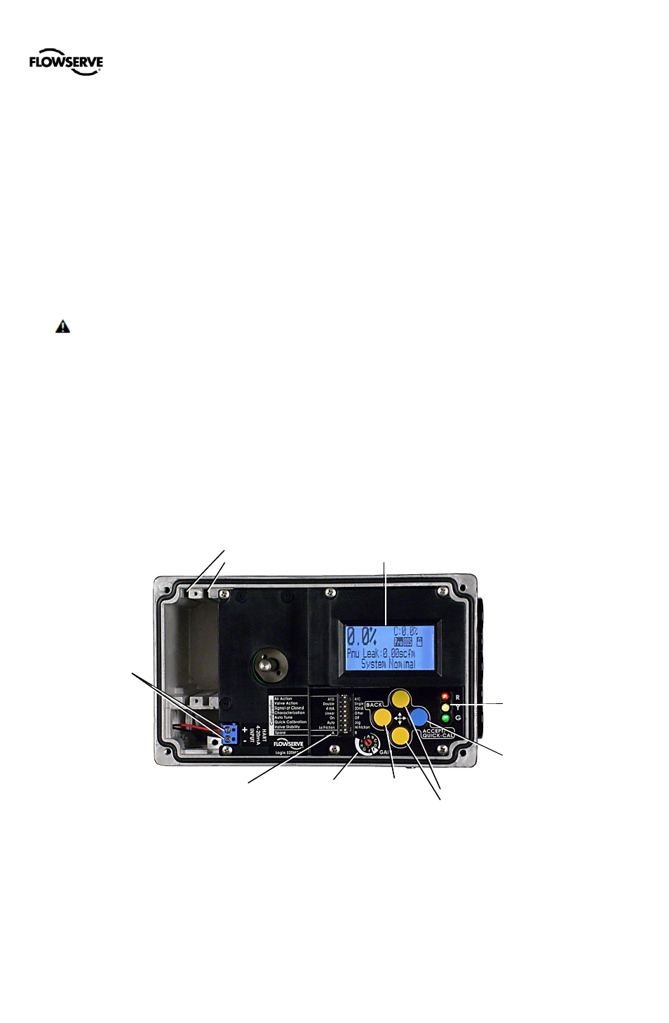
Figure 31: Local User Interface
Display
LED Status
Lights
QUICK-CAL/
ACCEPT Button
UP Button
DOWN Button
Selectable
GAIN Switch
Configuration
Switches
BACK
Button
HART
4-20 mA
Input
Card Slot 2
Card Slot 1