4 vented design, Ented, Esign – Flowserve 500+ Series Logix User Manual
Page 21
User Instructions - Logix® 500+ Series Digital Positioners FCD LGENIM0105-10 11/13
flowserve.com
21
relay is used, a special procedure can be performed to
configure the positioner to purge properly using port A.
Contact your local Flowserve Representative for more
information regarding the purging option.
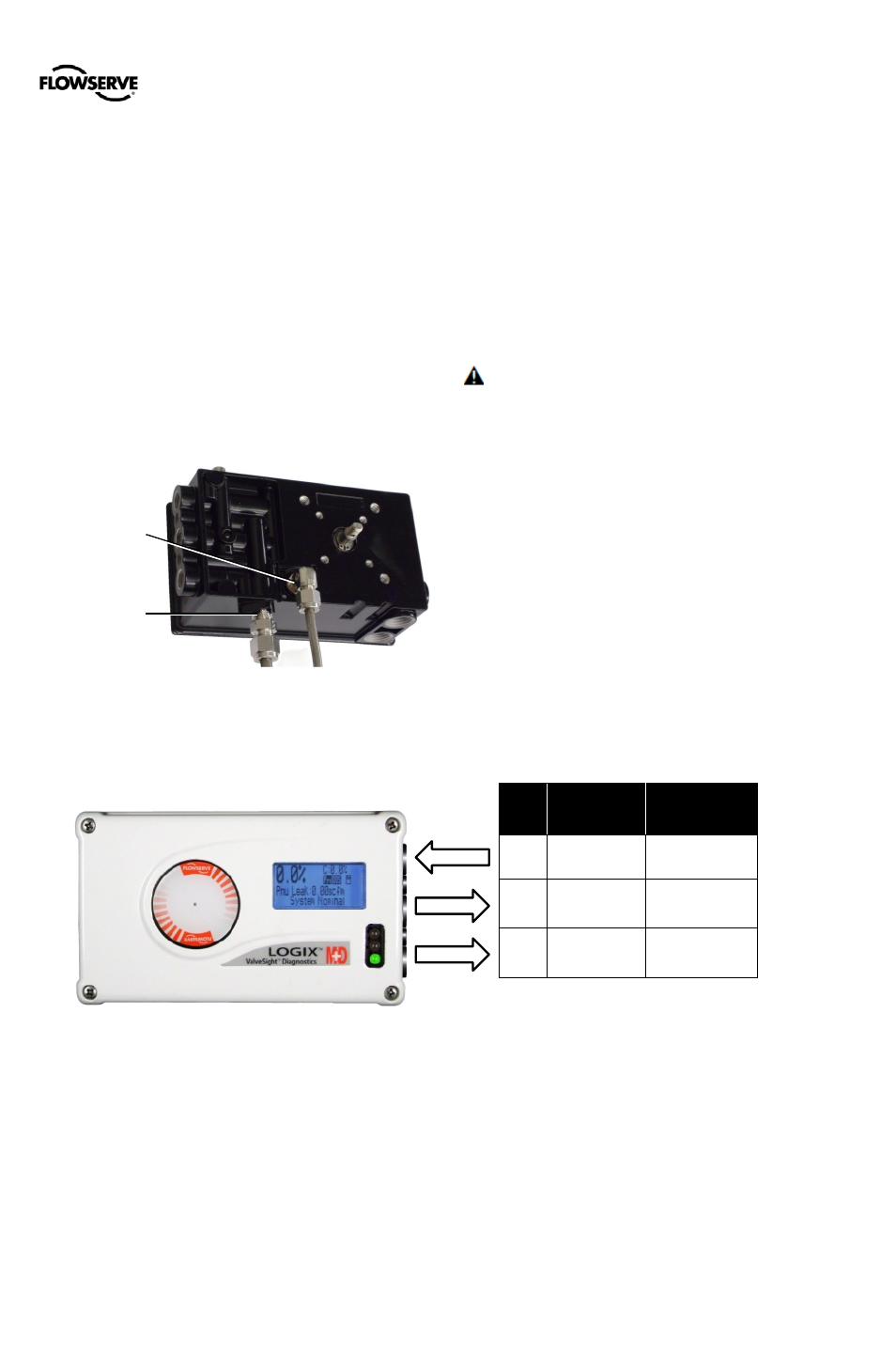
6.4
Vented Design
A standard Logix 500+ positioner is vented directly to the
atmosphere. When supply air is substituted with sweet
natural gas, piping must be used to route the exhausted
natural gas to a safe environment.
The housing chamber exhaust port is located on the
backside of the positioner. The actuator exhaust port is
located on the bottom of the positioner. Both ports are
tapped with either ¼ NPTF or G ¼ threads and covered with
a protective cap. To control vented gas, remove the caps
and connect the necessary tubing/piping to these ports. See
Figure 21: Exhaust Vents.
Figure 21: Exhaust Vents
Figure 22: Pneumatic Connections
This piping system may cause some positioner back
pressure. Back pressure in the housing chamber is from the
modulator and regulator. Back pressure in the exhaust port
is from the actuator.
The maximum allowable back pressure from the housing
chamber is 0.14 barg (2.0 PSIG). For flow rates, see section
2.2 Air Supply.
The maximum allowable back pressure from the exhaust port
is 0.55 barg (8.0 PSIG) for double acting relays and is 0.14
barg (2.0 PSIG) for single acting relays. Higher pressure
may result in decreased performance. For output flow rates,
see section 2.3 Pneumatic Output.
CAUTION: The back pressure in the main housing must
never rise above 0.14 barg (2.0 PSIG). This could cause the
positioner to become unresponsive under some
circumstances.
Port
Single Acting
Poppet Style
Relay
Double Acting
Spool Style
Relay
S
Supply
Supply
B
Y1
Y2
A
(Plug)
Y1
Housing
Chamber
Exhaust
(0.14 barg Max)
Actuator
Exhaust
(0.55 barg Max)