Flowserve M-series PolyChem User Manual
Page 46
USER INSTRUCTIONS PolyChem M-SERIES ENGLISH 71569218 07-11
flowserve.com
Page 46 of 60
®
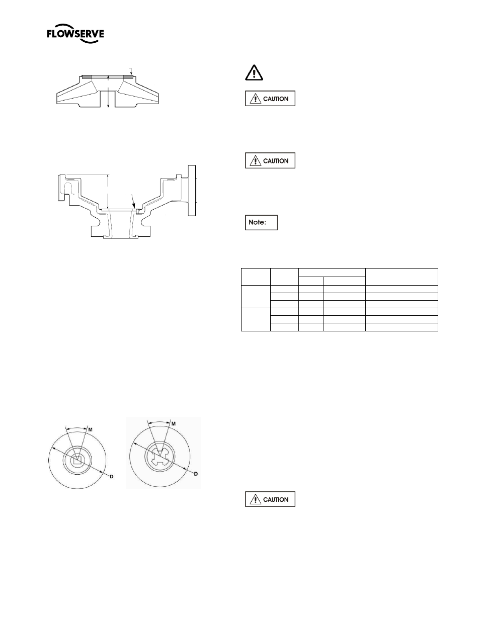
Figure 6-35: Impeller
Figure 6-36: Casing
6.8.2
Impeller drive
a)
The condition of the impeller drive mechanism
should be checked whenever maintenance is
performed.
b)
Measure the circumferential movement “M” of
the impeller when it is mounted on the shaft.
c)
Verify the impeller diameter “D”.
d)
Substitute values “M” and “D” into the equation
and if the answer is less than or equal to 10 then
the impeller can be reused.
M ÷ (0.017 x (D ÷ 2))
≤ 10 Reuse the impeller
> 10 Replace impeller or insert
Figure 6-37: Impeller Drive Check
6.8.3
Magnetic Coupling
MAGNETIC FIELD PRESENT
Do not use the silicon carbide shaft to
check the torque rating of the magnetic coupling. If
the magnetic coupling must be checked, a metallic
shaft similar to that shown in section 6.4 (Tools
required) must be substituted.
There are a total of six magnetic
couplings. Three for the Group A and 1 pumps and
three for the Group B and 2 pumps. It is imperative
that the appropriate inner magnet assembly be
matched with the corresponding outer magnet.
This test can only be performed on a long-
coupled pump, you must have a means to prevent the
rotation of the outer magnet.
Figure 6-38: Magnetic Coupling Torques
Pump
Group
Pump
Prefix
Magnet
Torque at 20°C (68°F)
N-m (lbf-in)
Poles
Length
A & 1
PA
8
31.8 (1.25)
18 (160)
PB
12
31.8 (1.25)
26 (230)
PC
12
63.5 (2.50)
61 (540)
B & 2
PJ
10
63.5 (2.50)
47 (420)
PK
16
63.5 (2.50)
77 (680)
PL
16
86.4 (3.40)
111 (983)
Note: Length dimensions shown in millimeters (inches).
a)
Reassemble the pump (see section 6.9)
substituting a metallic shaft (see section 6.4) for
the silicon carbide shaft.
b)
Install the Flowserve impeller wrench and key
onto the input shaft of the pump. The wrench
handle should be touching the workbench
towards the right as you are facing the suction
flange of the pump.
c)
Utilizing a torque wrench and socket (an
extension may be necessary) place it onto the
hex head protruding from the end of the metallic
shaft.
d)
Rotate the wrench and determine if you can
achieve the torque values shown in Figure 6-37
for the magnetic coupling being evaluated.
Do not exceed the values listed in
Figure 6-38.
e)
If the noted value is obtained you can reuse the
coupling provided there is no other damage. If
on the other hand the value was not reached you
Thrust
Bearing
Width
Depth
Thrust
Bearing
Thrust
Bearing
Height