4 performance and operation limits – Flowserve M-series PolyChem User Manual
Page 13
USER INSTRUCTIONS PolyChem M-SERIES ENGLISH 71569218 07-11
flowserve.com
Page 13 of 60
®
3.3.10 Driver
The driver is normally an electric motor. Different
drive configurations may be fitted such as internal
combustion engines, turbines, hydraulic motors etc
driving via couplings, belts, gearboxes, drive shafts
etc.
3.3.11 Accessories
Accessories may be fitted when specified by the
customer.
3.4 Performance and operation limits
This product has been selected to meet the
specification of your purchase order. See section 1.5.
The following data is included as additional information
to help with your installation. It is typical, and factors
such as liquid being pumped, temperature, and material
of construction may influence this data. If required, a
definitive statement for your application can be obtained
from Flowserve.
3.4.1
Material cross reference chart
Figure 3-3 is the material cross-reference chart for all
PolyChem M-series pumps.
3.4.2
Pressure-temperature ratings
PN 16 flanges are standard for the ISO model pump
while Class 150 flanges are standard for the ANSI
model. Refer to Figure 3-4A and 3-4B for each
pump
’s pressure-temperature (P-T) rating.
The maximum discharge pressure must be less
than or equal to the P-T rating. Discharge pressure
may be approximated by adding the suction pressure
to the differential pressure developed by the pump.
3.4.3
Suction pressure limits
The suction pressure limits for PolyChem M-series
pumps is limited by the P-T rating.
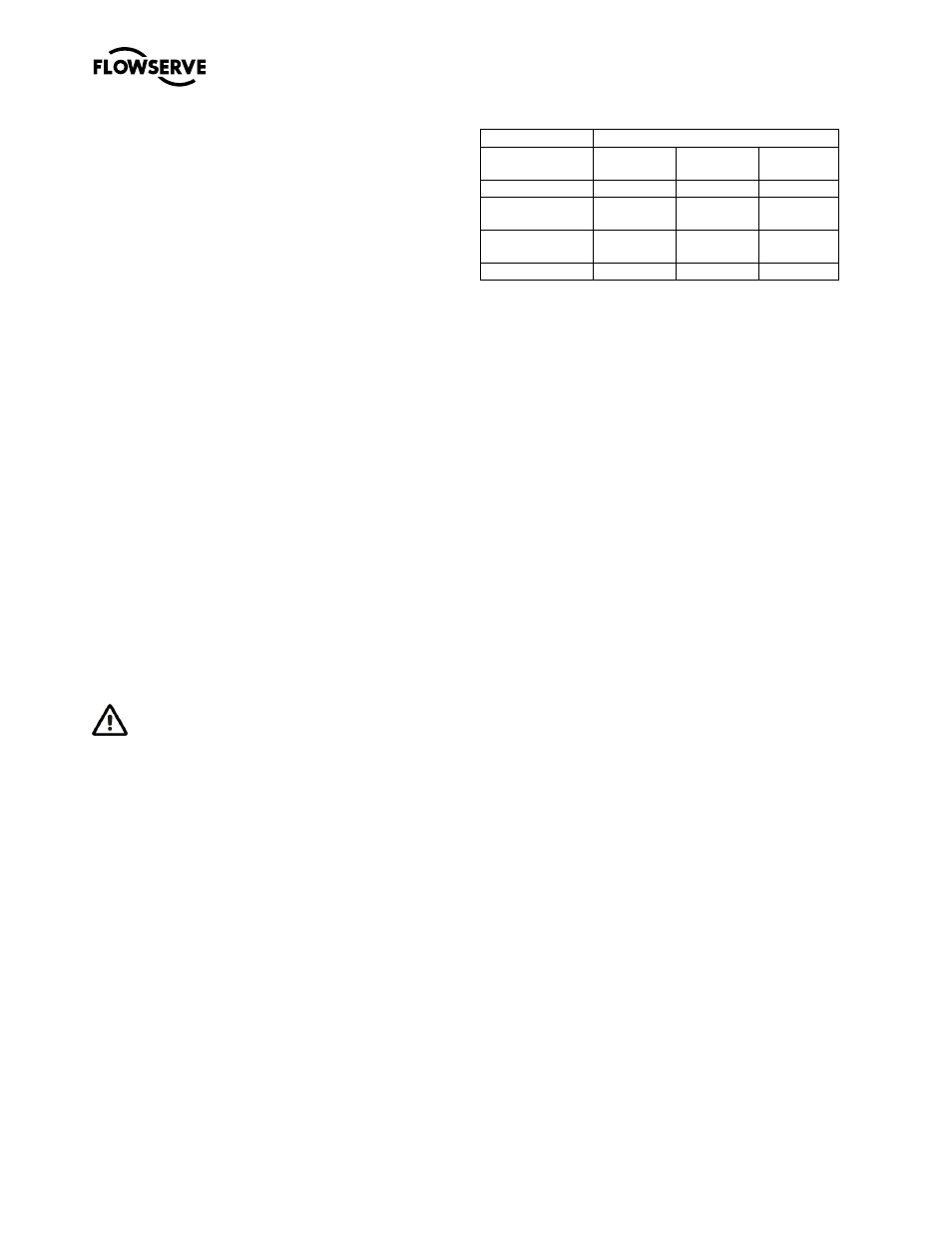
3.4.4
Minimum continuous flow
The minimum continuous flow (MCF) is based on a
percentage of the best efficiency point (BEP). Figure
3-2 identifies the MCF for all PolyChem M-series
pumps.
Figure 3-2: Minimum continuous flow
MCF % of BEP
Pump Size
3500/2900
rpm
1750/1450
rpm
1180/960
rpm
P_3x2-6
20%
10%
10%
P_3x2-10
P_50-250
30%
10%
10%
P_4x3-10
P_65-250
N/A
10%
10%
All other sizes
10%
10%
10%