Flowserve ESP3 User Manual
Page 23
ESP3 USER INSTRUCTIONS ENGLISH 26999943 08-11
Page 23 of 64
4.8 Final free rotation check
After connecting the piping, rotate the pump drive
shaft clockwise (viewed from motor end) by hand
several complete revolutions to be sure there is no
binding and that all parts are free. If piping caused
unit to be in a bind, correct piping to relieve strain
on the pump.
4.9 Auxiliary piping
Check to see if any other connections need to be
made to pump, such as fluid injection to stuffing
box for seal or packing lubrication (when furnished)
and make the required connections.
Check to see that connections are made to the
lubrication fittings at pump manifold [3869] on
mounting plate [6130]
4.10 Electrical connections
Electrical connections must be made
by a qualified Electrician in accordance with
relevant local national and international regulations.
It is important to be aware of the EUROPEAN
DIRECTIVE on potentially explosive areas where
compliance with IEC60079-14 is an additional
requirement for making electrical connections.
It is important to be aware of the EUROPEAN
DIRECTIVE on electromagnetic compatibility when
wiring up and installing equipment on site.
Attention must be paid to ensure that the techniques
used during wiring/installation do not increase
electromagnetic emissions or decrease the
electromagnetic immunity of the equipment, wiring or
any connected devices. If in any doubt contact
Flowserve for advice.
The motor must be wired up in
accordance with the motor manufacturer's
instructions (normally supplied within the terminal
box) including any temperature, earth leakage,
current and other protective devices as appropriate.
The identification nameplate should be checked to
ensure the power supply is appropriate.
See section 5.4, Direction of rotation
before connecting the motor to the electrical supply.
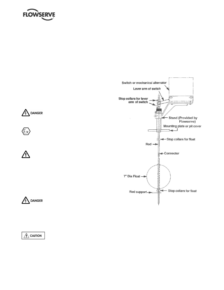
4.11 Level controls
Assemble float control equipment per Figure 4-3
below. Wire the float controls following the
diagrams on the next several pages. The stops
should be set in accordance with maximum and
minimum liquid levels desired and required. Float
rods are furnished in kits of a standard length. The
rod might have to be cut off to fit the particular
installation.
Figure 4-3
Some of the wiring diagrams are included on the
following pages. If the wiring diagram needed is not
included, contact control manufacturer for wiring
instructions.