10 assembly, Assembly (6.10), Reassembly (6.10, assembly) – Flowserve CPX IDP User Manual
Page 29
CPX, CPXR, CPXN and CPXP USER INSTRUCTIONS ENGLISH 71569117 09-11
Page 29 of 44
flowserve.com
6.9.3 Gaskets and O-rings [4590, 4610]
After dismantling, discard and replace.
6.9.4 Bearings [3011, 3013]
It is recommended that bearings are not re-used after
any removal from the shaft.
The bearings and lubricant are to be inspected for
contamination and damage. If oil bath lubrication is
utilized, these provide useful information on operating
conditions within the bearing housing.
If bearing damage is not due to normal
wear and the lubricant contains adverse
contaminants, the cause should be corrected before
the pump is returned to service.
6.9.5 Bearing labyrinths/isolators [4330]
Labyrinth seals and bearing isolators should be
inspected for damage but are normally non-wearing
parts and can be re-used.
Bearing seals are not totally leak free devices. Oil from
these may cause staining adjacent to the bearings.
6.9.6 Bearing housing and carrier [3200, 3240]
Inspect the bearing carrier circlip groove. Ensure it is
free from damage and that housing lubrication
passages are clear.
Replace grease nipples or the filter breather (where
fitted) if damaged or clogged. On oil lubricated
versions, the oil level sight glass [3856] should be
replaced if oil stained.
6.10 Assembly
To assemble the pump consult the sectional
drawings. See section 8, Parts lists and drawings.
Ensure threads, gasket and O-ring mating faces are
clean. Apply thread sealant to non-face sealing pipe
thread fittings.
6.10.1 Bearing housing and rotating element
assembly
a) Clean the inside of the bearing housing [3200],
bearing carrier [3240] and bores for bearings.
b) Attach bearing housing support foot [3134].
c) Fit the thrust ball bearing [3013] on to shaft [2100].
The double row thrust bearing will not normally
have a single filling slot, as such bearings are
limited to taking thrust in only one direction.
If such a bearing replacement is used, it
must be positioned on the shaft so that the bearing
filling slot faces the impeller end of the shaft.
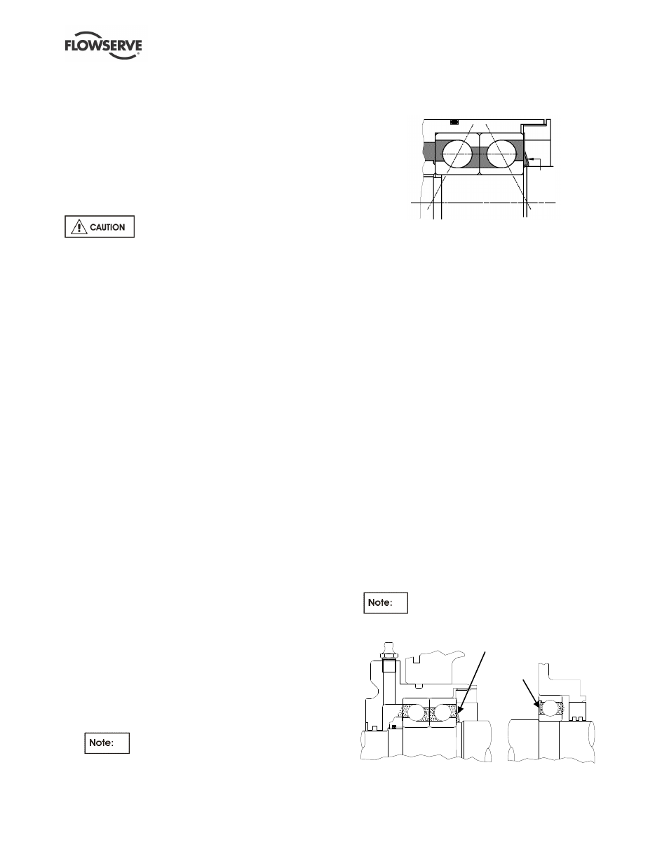
d) If the pair of angular contact thrust bearings are
to be fitted, these must be mounted back-to-back,
as shown below:
Grease
retainer
[3864]
Grease retainer (clearance type) is only fitted
on grease lubricated units
The following methods are recommended for
fitting the bearings onto the shaft:
Method 1: Use a hotplate, hot bath, oven or
induction heater to heat the bearing race so it can
easily be placed in position then allowed to shrink
and grip the shaft. It is important that the
temperature is not raised above 100 ºC (212 ºF).
Method 2: Press the bearing onto the shaft
using equipment that can provide a steady, even
load to the inner race. Take care to avoid
damaging the bearing and shaft.
e) With bearings at ambient temperature, screw on
to the shaft the self-locking bearing locknut
[3712.1] (with its polyamide insert facing away
from the bearing) until tight.
f) With double row thrust bearings place the
bearing circlip [6544] over the shaft, with the
tapered face facing the impeller end.
g) With the pair of angular contact thrust bearing
option, the bearing locknut [3712.2] (and Nilos
ring [3864] if grease lubricated unit) should be
placed placed on the shaft before fitting the pump
radial bearing, having the larger diameter end
facing the impeller end.
h) Fit pump radial ball bearing [3011] onto the shaft
using Method 1 or 2 above.
i)
With the NUP roller bearing option, the loose ring
should be against the shaft shoulder.
On grease lubricated units the bearing
shields shall be facing the other bearing. (See
below.)
Nilos ring
Shield