Flowserve CPX IDP User Manual
Page 17
CPX, CPXR, CPXN and CPXP USER INSTRUCTIONS ENGLISH 71569117 09-11
Page 17 of 44
flowserve.com
Size
Forces in N (lbf)
Moments in Nm
(lbf•ft)
Suction
Discharge
Suction
Discharge
Mx
My
Mz
Fx
Fy
Fz
Mx
My
Mz
Fx
Fy
Fz
ƩM
ƩF
ƩM
ƩF
150-125CPX315
4 710
(3 470)
2 360
(1 740)
3 540
(2 610)
6 280
(1 410)
5 020
(1 130)
4 080
(920)
4 710
(3 470)
2 360
(1 740)
3 540
(2 610)
5 020
(1 130)
4 090
(920)
6 280
(1 410)
6 350
(4 680)
9 020
(2 030)
6 350
(4 680)
9 020
(2 030)
200-150CPX315
6 990
(5 160)
3 500
(2 580)
5 240
(3 870)
9 460
(2 130)
7 550
(1 700)
6 150
(1 380)
4 710
(3 470)
2 360
(1 740)
3 540
(2 610)
5 020
(1 130)
4 090
(920)
6 280
(1 410)
9 410
(6 940)
13 580
(3 050)
6 350
(4 680)
9 020
(2 030)
100-65CPX400
2 670
(1 970)
1 340
(990)
2 000
(1 480)
3 570
(800)
2 850
(640)
2 320
(520)
1 210
(890)
600
(440)
900
(660)
1 350
(300)
1 100
(250)
1 690
(380)
3 600
(2 660)
5 120
(1 150)
1 620
(1 190)
2 430
(550)
125-80CPX400
4 710
(3 470)
1 740
(1 280)
3 540
(2 610)
4 650
(1 050)
5 020
(1 130)
3 020
(680)
1 310
(970)
710
(520)
1 010
(740)
1 850
(420)
1 500
(340)
2 300
(520)
6 140
(4 530)
7 480
(1 680)
1 800
(1 330)
3 310
(740)
150-125CPX400
4 710
(3 470)
2 360
(1 740)
3 540
(2 610)
6 280
(1 410)
5 020
(1 130)
4 080
(920)
2 670
(1 970)
990
(730)
2 000
(1 480)
2 110
(470)
2 320
(520)
3 570
(800)
6 350
(4 680)
9 020
(2 030)
3 480
(2 570)
4 750
(1 070)
200-150CPX400
6 990
(5 160)
3 500
(2 580)
5 240
(3 870)
9 460
(2 130)
7 550
(1 700)
6 150
(1 380)
4 710
(3 470)
2 360
(1 740)
3 540
(2 610)
5 020
(1 130)
4 090
(920)
6 280
(1 410)
9 410
(6 940)
13 580
(3 050)
6 350
(4 680)
9 020
(2 030)
250-200CPX400
9 950
(7 340)
4 980
(3 670)
7 460
(5 500)
13 420
(3 020)
10 730
(2 410)
8 720
(1 960)
6 990
(5 160)
3 500
(2 580)
5 240
(3 870)
7 560
(1 700)
6 150
(1 380)
9 460
(2 130)
13 400
(9 880)
19 270
(4 330)
9 410
(6 940)
13 580
(3 050)
200-150CPX500
6 990
(5 160)
3 500
(2 580)
5 240
(3 870)
9 460
(2 130)
7 550
(1 700)
6 150
(1 380)
4 710
(3 470)
2 360
(1 740)
3 540
(2 610)
5 020
(1 130)
4 090
(920)
6 280
(1 410)
9 410
(6 940)
13 580
(3 050)
6 350
(4 680)
9 020
(2 030)
4.6.5 Auxiliary piping
The connections that are to be piped
up will have been fitted with protective metal or
plastic plugs which will need to be removed.
4.6.5.1
CPX, CPXR and CPXN pumps fitted with
packed glands
When suction pressure is below ambient pressure
and differential head is less than 10 m (32.8 ft), it may
be necessary to feed gland packing with liquid to
provide lubrication and prevent the ingress of air.
4.6.5.2
Pumps fitted with mechanical seals
The conical design of the cover provides excellent
liquid circulation around the seal and will not normally
require a separate flush for single internal seals.
Single seals requiring re-circulation will normally be
provided with the auxiliary piping from pump casing
already fitted.
Flowserve seal connections are designated as follows:
Q
- quench
F
- flush
D
- drain outlet
BI - barrier fluid in (double seals)
BO - barrier fluid out (double seals)
H
- heating jacket
C
- cooling jacket
Covers having an auxiliary quench connection,
require connection to a suitable source of liquid flow,
low pressure steam or static pressure from a header
tank. Recommended pressure is 0.35 bar (5 psi) or
less. Check General arrangement drawing.
Dual seals, both pressurised and unpressurised,
require a barrier liquid between the seals, compatible
with the pumped liquid.
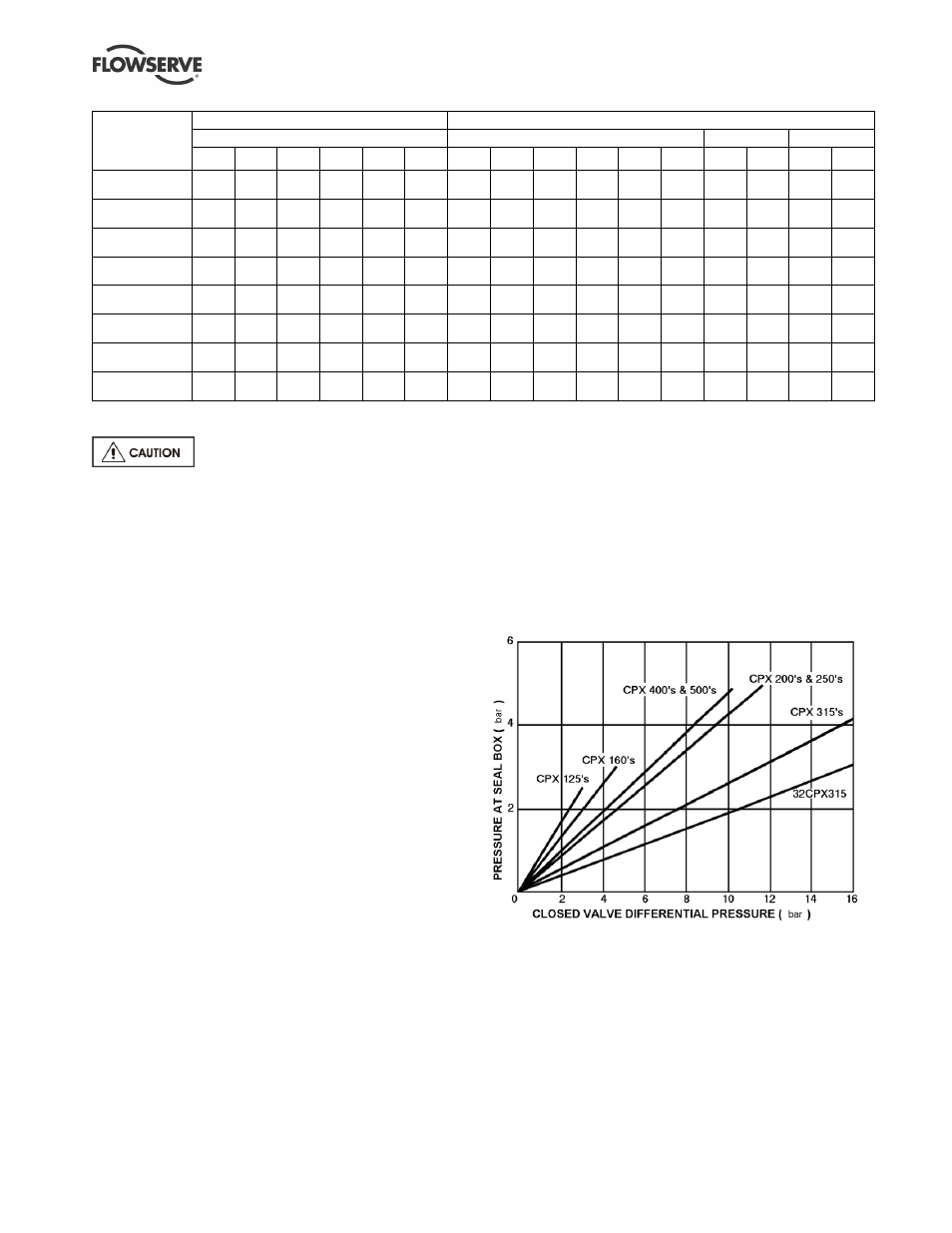
With back-to-back double seals, the barrier liquid
should be at a minimum pressure of 1 bar (14.5 psi)
above the maximum pressure on the pump side of
the inner seal. (See chart.) The barrier liquid
pressure must not exceed limitations of the seal on
the atmospheric side. For toxic service the barrier
liquid supply and discharge must be handled safely
and in line with local legislation.
Notes
:
a) Total seal pressure is equal to pressure at seal plus suction
pressure.
b) For pumped liquid viscosities greater than 440 Centistokes
multiply the differential pressure by 1.25 for 125, 160 and 200
size pumps and by 2.0 for larger sizes.
c) Differential pressure in bar equals head in metres multiplied by
specific gravity all divided by 10.19.
d) Ensure to check the seal minimum and maximum pressure
limits are not exceeded and the pressure is agreed with
Flowserve.