6 piping, Piping (4.6) – Flowserve CPX IDP User Manual
Page 14
CPX, CPXR, CPXN and CPXP USER INSTRUCTIONS ENGLISH 71569117 09-11
Page 14 of 44
flowserve.com
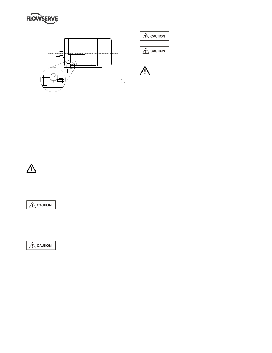
4.5.3 Check for soft foot
This is a check to ensure that there is no undue
stress on the driver holding down bolts; due to non-
level baseplate or twisting. To check, remove all
shims and clean surfaces and tighten down driver to
the baseplate. Set a dial indicator as shown in sketch
and loosen off the holding down bolt while noting any
deflection reading on the dial test Indicator - a
maximum of 0.05 mm (0.002 in.) is considered
acceptable but any more will have to be corrected by
adding shims. For example, if the dial test indicator
shows the foot lifting 0.15 mm (0.006 in.) then this is
the thickness of shim to be placed under that foot.
Tighten down and repeat the same procedure on all
other feet until all are within tolerance.
Complete piping as below and see sections 4.7,
Final shaft alignment check up to and including section
5, Commissioning, startup, operation and shutdown,
before connecting driver and checking actual rotation.
4.6 Piping
Protective covers are fitted to the pipe
connections to prevent foreign bodies entering during
transportation and installation. Ensure that these
covers are removed from the pump before connecting
any pipes.
4.6.1 Suction and discharge pipework
Never use pump as a support for
piping.
Maximum forces and moments allowed on the pump
flanges vary with the pump size and type. To minimize
these forces and moments that may, if excessive, cause
misalignment, hot bearings, worn couplings, vibration
and the possible failure of the pump casing, the
following points should be strictly followed:
Prevent excessive external pipe load
Never draw piping into place by applying force to
pump flange connections
Do not mount expansion joints so that their force,
due to internal pressure, acts on the pump flange
Ensure piping and fittings are flushed
before use.
Take any suction lift into account in
the available NPSH which must be higher than the
required NPSH of the pump.
Ensure piping for hazardous liquids is arranged
to allow pump flushing before removal of the pump.
4.6.1.1
CPX, CPXR and CPXN only
In order to minimize friction losses and hydraulic
noise in the pipework it is good practice to choose
pipework that is one or two sizes larger than the
pump suction and discharge. Typically main
pipework velocities should not exceed 2 m/s (6 ft/sec)
suction and 3 m/s (9 ft/sec) on the discharge.
4.6.1.2
CPXP self primer only
The delivery pipework must permit priming air to
escape unhindered from the pump during the priming
cycle, without back pressure and prevent excessive
run-back of liquid on shutdown to minimise syphoning.
Priming air may be vented in one of the following ways:
1. The discharge pipework regulating valve, if fitted,
may be partly opened during the priming cycle to
freely vent the air.
2. An automatic air release valve may be fitted to the
discharge pipework, between the pump and any
valves, providing that gases and vapours given off
are environmentally safe and acceptable for
release into the atmosphere.
3. An air bleed pipe may be run from the discharge
pipework, between the pump and any valves, back
to the suction tank or sump. This arrangement will
require a manual or automatic control during normal
operation to prevent continuous re-circulation of the
pumped liquid.
4.6.2 Suction piping
4.6.2.1
CPX, CPXR and CPXN suction piping
a) The inlet pipe should be one or two sizes larger
than the pump inlet bore and pipe bends should
be as large a radius as possible.
b) On suction lift the piping should be inclined up
towards the pump inlet with eccentric reducers
incorporated to prevent air locks.
c) On positive suction, the inlet piping must have a
constant fall towards the pump.
d) The pipe next to the pump should be the same
diameter as the pump suction and have a minimum
of two pipe diameters of straight section between
the elbow and the pump inlet flange. Where the