Warning, Service & maintenance, Important – Echo Bear Cat 70385 User Manual
Page 42: Replacing the shredder knives, Shredder kit parts list, Installation steps, Fig. #47, Fig. #46
Page 36
Bear Cat Chipper Shredder Operator’s Manual
The Rectangular Shredder Knife Kit is a replacement kit to
replace existing dull or damaged knives. The serrated shred-
der knives are designed to offer long life and can be reversed
if they become dull. To remove the knives or to install a
complete new shredder kit proceed as follows.
INSTALLATION STEPS:
1.
Remove belt guards from under engine frame, remove
discharge cover and screen.
2.
Remove #10-24 nuts and bolts from knife shafts.
3.
Align shaft with 5/8” hole in rear of frame and small hole
in front of machine by the chipper chute.
4.
Using a small punch or rod drive the shaft towards and
out the rear 5/8” hole.
5.
To assemble, insert shaft through the 5/8” hole in rear of
frame and slide knives and spacers in their proper order
(see drawing) onto the shaft. Install a new # 10-24 nut
and bolt.
6.
Repeat steps 3 through 6 to assemble the other three
shafts.
7.
When completed install discharge screen, and dis-
charge cover, torque all 3/8” bolts to 33 ft lbs. and test
run machine.
This shredder kit uses an improved knife pattern to pro-
vide more complete shredding, durability, and easier feed-
ing. Insure the knives and spacers are installed properly
to maintain rotor balance.
NOTE
The serrated edge of the shredder knives should face the
same direction as the cutting edge of the chipper blades.
Never reuse the #10-24 nut and bolt, always install new
parts when repairing. Never reuse shafts or spacers if
they show signs of wear or abuse. Install new ones.
IMPORTANT
SHREDDER KIT PARTS LIST
SHREDDER KIT PARTS LIST
REPLACING THE SHREDDER KNIVES
4
3
6
7
4
5
4
5
4
1
2
6
7
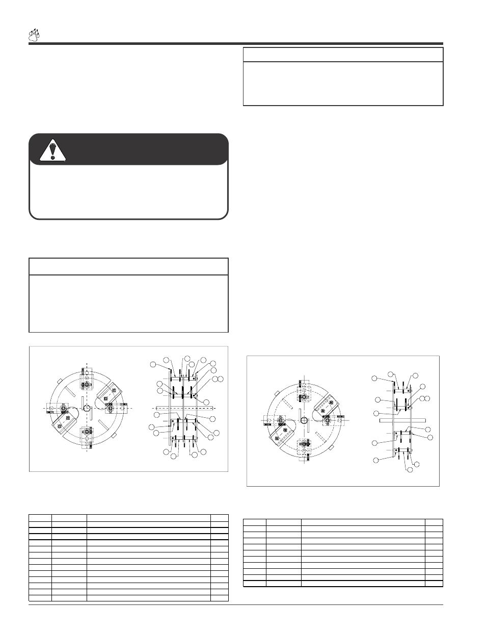
SHAFT ONE
SHAFT TWO
SHAFT THREE
SHAFT FOUR
8
SHAFT
ONE
SHAFT
THREE
SHAFT
TWO
SHAFT
FOUR
IMPORTANT
SHAFT ONE AND SHAFT THREE ARE SYMMETRICAL
SHAFT TWO AND SHAFT FOUR ARE SYMMETRICAL
RECTANGULAR SHREDDER KNIFE KIT
TYPICAL SETUP FOR MODEL 70050
Fig. #47
1
3
2
4
4
4
5
5
6
6
7
7
8
9
9
10
11
11
12
SHAFT ONE
SHAFT TWO
SHAFT THREE
SHAFT FOUR
4
12
8
SHAFT ONE AND SHAFT THREE ARE SYMMETRICAL
SHAFT TWO AND SHAFT FOUR ARE SYMMETRICAL
IMPORTANT
RECTANGULAR SHREDDER KNIFE KIT
TYPICAL SETUP FOR ALL 8 HP MODELS
SHAFT
ONE
SHAFT
TWO
SHAFT
FOUR
SHAFT
THREE
Fig. #46
ITEM #
PART #
DESCRIPTION
QTY
1
15397
NUT, 10/24 NYLOCK TYPE NM, ZP
4
2
15459
SKT HD CAP SCW #10-24 X 1-3/8"PL
4
3
70064
C/S KNIFE SHAFT
4
4
70533
SPACER, 0.75 X 2.170
4
5
70534
SPACER, 0.75 X 0.620
2
6
70535
SPACER, 0.75 X 1.850
2
7
70536
SPACER, 0.75 X 1.240
2
8
70537
SPACER, 1.00 X 1.700 (W/HOLE)
2
9
70538
SPACER, 1.00 X 1.240 (W/HOLE)
2
10
70856
SHREDDING KNIFE, RECTANGULAR
12
11
70967
KNIFE, ROTOR BALANCE
2
12
70968
SPACER, .81 X .620
2
13
70976
INSTRUCTIONS, WIDE SHRED KIT (THIS INST. SHEET)
1
ITEM #
PART #
DESCRIPTION
QTY
1
15397
NUT, 10/24 NYLOCK TYPE NM, ZP
4
2
15459
SKT HD CAP SCW #10-24 X 1-3/8" PL
4
3
70031
KNIFE SHAFT
4
4
70533
SPACER, 0.75 X 2.170
4
5
70534
SPACER, 0.75 X 0.620
2
6
70537
SPACER, 1.00 X 1.700 (W/HOLE)
2
7
70538
SPACER, 1.00 X 1.240 (W/HOLE)
2
8
70856
SHREDDING KNIFE, RECTANGULAR
8
9
71382
KNIFE, ROTOR BALANCE
2
10
71383
INSTRUCTIONS, SHREDDER KIT (THIS INST. SHEET)
1
To prevent personal injury or property damage: Shut
off engine, disconnect spark plug wire and make sure
that all moving parts have come to a complete stop
before, servicing, adjusting or repairing.
WARNING
Service & Maintenance