Important, Warning, Assembly – Echo Bear Cat 70385 User Manual
Page 27: Assembly instructions (all “s” models), Figure # 20 wide discharge assembly, Figure # 21 narrow discharge assembly
Page 21
Bear Cat Chipper Shredder Operator’s Manual
Assembly
ASSEMBLY INSTRUCTIONS (ALL “S” MODELS)
If any bolts or nuts are dropped in the shredder be sure to
remove them before starting the machine. Remove items
from the shredder area by removing the discharge screen.
IMPORTANT
To prevent personal injury or property damage: Shut off
engine, disconnect spark plug wire, remove ignition key
and make sure that all moving parts have come to a
complete stop, before servicing, adjusting or repairing.
WARNING
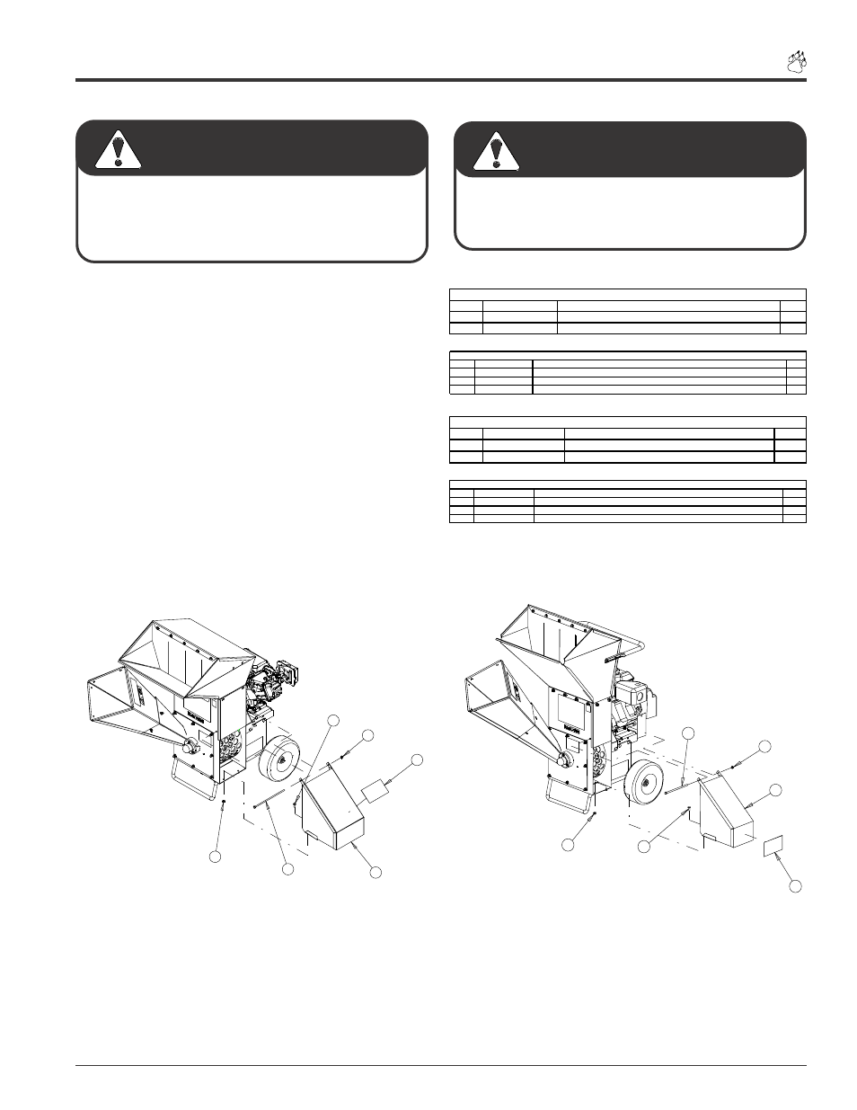
STEP # 4: INSTALLING THE WIDE AND
NARROW DISCHARGE ASSEMBLY
1
2
3
5
4
4
Figure # 20 Wide Discharge Assembly
1
2
3
4
4
5
Figure # 21 Narrow Discharge Assembly
ITEM
PART NUMBER
DESCRIPTION
QTY
1
12175
DECAL, INLET AND DISCHARGE
1
2
71389
WELDMENT, NARROW EUROPEAN DISCHARGE
1
NARROW EUROPEAN DISCHARGE ASSEMBLY (71773)
ITEM
PART NUMBER
DESCRIPTION
QTY
3
15003
BOLT, 5/16" X 3/4" GR5 HEX CAPSCREW ZP (LOCATED IN OWNERS KIT)
2
4
15356
NUT, 5/16" NE NYLOCK ZP (LOCATED IN OWNERS KIT)
3
5
15407
BOLT, 5/16" X 7-1/2" HHCS NC GR5 ZP (LOCATED IN OWNERS KIT)
1
MISCELLANEOUS NARROW EUROPEAN DISCHARGE ASSEMBLY PARTS
ITEM
PART NUMBER
DESCRIPTION
QTY
1
12175
DECAL, INLET AND DISCHARGE
1
2
71386
WELDMENT, WIDE EURO DISCHARGE
1
WIDE EUROPEAN DISCHARGE ASSEMBLY (71776)
ITEM
PART NUMBER
DESCRIPTION
QTY
3
15003
BOLT, 5/16" X 3/4" GR5 HEX CAPSCREW ZP (LOCATED IN OWNERS KIT)
2
4
15356
NUT, 5/16" NE NYLOCK ZP (LOCATED IN OWNERS KIT)
3
5
15408
BOLT, 5/16" X 10" HHCS NC GR5 ZP (LOCATED IN OWNERS KIT)
1
MISCELLANEOUS WIDE EUROPEAN DISCHARGE ASSEMBLY PARTS
8. Place the respective discharge weldment onto the chip-
per. The holes on the weldment should line up with holes
on the chipper as shown in Figures #20 and #21.
9. Place the 5/16” X 7 1/2” (Narrow) or the 5/16” X 10”
(Wide) bolt through the corresponding holes that attach
the top of the weldment to the chipper. Secure with a
5/16” nut tighten to the proper torque.
10.To secure the bottom of the weldment to the chipper,
place a 5/16” X 3/4” bolt into each hole. Secure with a
5/16” nut tighten to the proper torque.