Important, Warning, Assembly – Echo Bear Cat 70385 User Manual
Page 25: Hg f, Hardware, Parts not shown actual size)
Page 19
Bear Cat Chipper Shredder Operator’s Manual
Assembly
ASSEMBLY INSTRUCTIONS (ALL MODELS)
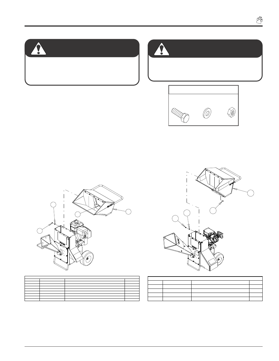
STEP # 2: INSTALLING THE HOPPER
3. Assemble the hopper assembly to the frame so the handle
is located above the engine and the opening is toward
the chipper chute.
4. Install (Qty. 12) 5/16” X 3/4” bolts so the head of the bolt
is inside the hopper. Fasten bolts with the provided (Qty.
12) 5/16” flat washers and (Qty. 12) 5/16” nylock nuts.
5. Inspect the entire machine to insure all bolts, nuts, and
screws are tight. Refer to the torque chart for correct
settings. Read and understand all decals and instruc-
tions.
If any bolts or nuts are dropped in the shredder be sure to
remove them before starting the machine. Remove items
from the shredder area by removing the discharge screen.
IMPORTANT
To prevent personal injury or property damage: Shut off
engine, disconnect spark plug wire, remove ignition key
and make sure that all moving parts have come to a
complete stop, before servicing, adjusting or repairing.
WARNING
(Parts not shown actual size)
H
G
F
HARDWARE
ITEM
PART NUMBER
DESCRIPTION
QTY
J
15010
BOLT, 3/8" X 3-1/2" GR5 HHCS ZP
2
K
15031
WASHER, 3/8" FLAT ZP
2
L
15388
NUT, 3/8" NE NYLOCK ZP
2
M
16008
TIRE AND WHEEL ASSEMBLY 4.80 - 8
2
N
16264
BOLT, WHEEL .500-20 UNF X 1.437
8
O
17879
PIN, SNAP 3/8" X 1-1/8" USABLE LGH
1
P
70372
WELDMENT, HITCH JACK
1
Q
NPN
HITCH POLE
1
PARTS LIST
F
I
H
G
Figure #17
Figure. # 18
H
G
F
I
ITEM
PART NUMBER
DESCRIPTION
QTY
F
15003
BOLT, 5/16" X 3/4" HEX HEAD
12
G
15250
WASHER, 5/16" FLAT
12
H
15356
NUT, 5/16" NYLOCK
12
I
NPN
EUROPEAN HOPPER W/HANDLE
1
EUROPEAN HOPPER INSTALLATION