Assembly – DR Power Dual Action 15-Ton Gas (Aug 2011 - Present) User Manual
Page 9
CONTACT US AT www.DRpower.com 9
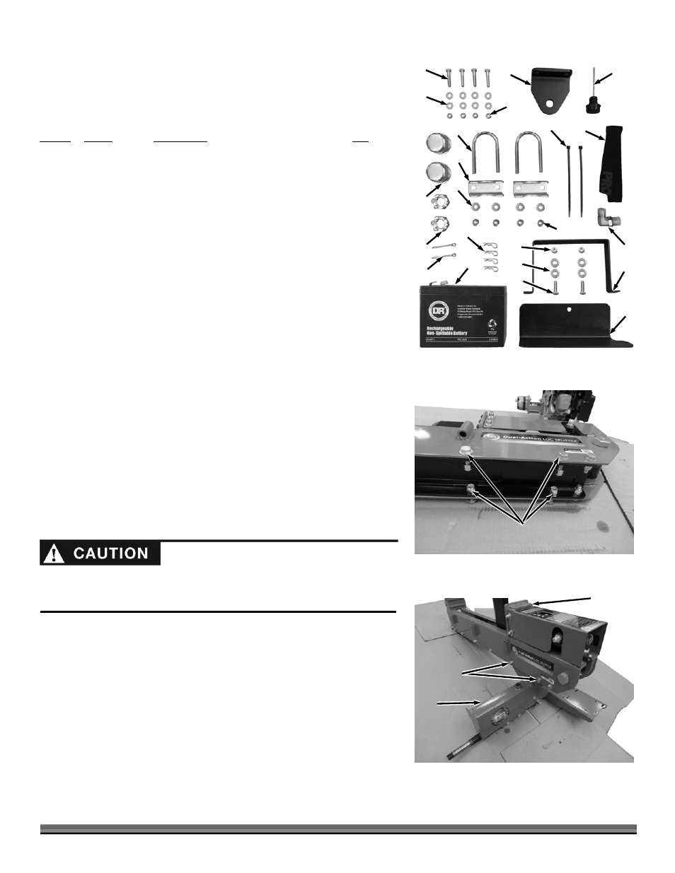
1. Open the Parts Box and lay them out on a clean flat area (Figure 2).
Note: For assembly location, the part numbers in the following list can be
referenced to the Parts List and illustrations in Chapter 6.
Parts Box (
Figure 2):
Item # Part
# Description
Qty
1 ............. 13443 .............. Bolt, HCS, 5/16-18 X 1-1/2, Gr5, ZP .............. 4
2 ............. 11238 .............. Washer, Flat, 1/4" USS .................................. 12*
3 ............. 11076 .............. Nut, Nylon Lock, 5/16-18, ZP ........................ 4
4 ............. 29054 .............. Mount, Tow Hitch, Rear ................................. 1
5 ............. 29367 .............. Dipstick ........................................................... 1
6 ............. 27610 .............. Abrasion Resistant Sheathing, 15.5in ............ 1
7 ............. 11214 .............. Cable Tie, 7-1/2 Long ..................................... 2
8 ............. 25616 .............. Hyd Adapter jcm08-obm08-90 ....................... 1
9** ......... 24230 .............. Strap, Battery .................................................. 1
10** ....... 29365 .............. Mount, Battery ................................................ 1
11** ....... 11149 .............. Bolt, HCS, 1/4-20 X 1.00, GR5, ZP ................ 2
12** ....... 11073 .............. Nut, Nylon Lock, 1/4-20, ZP .......................... 2
13** ....... 13447 .............. Battery, 12V, 9AH ........................................... 1
14 ........... 15192 .............. Pin, Hitch Clip, 5/16" - 3/8" ........................... 4
15 ........... 25311 .............. Pin, Cotter, 3/16" X 2.5" ................................. 2
16 ........... 25310 .............. Nut, Slotted, 1-14, ZP ..................................... 2
17 ........... 25318 .............. Cap, Dust ........................................................ 2
18 ........... 11075 .............. Nut, Nylon Lock, 3/8-16, ZP .......................... 4
19 ........... 11241 .............. Washer, Flat, 5/16 USS, ZP ........................... 4
20 ........... 29377 .............. Clamp, 2 inch, Jack ......................................... 2
21 ........... 29378 .............. U-bolt, 3/8-16 X 2 X 4, ZP .............................. 2
* Quantity of 8 for manual start Engine.
** Electric Start only.
Compare the contents of the Parts Box, Product Pack and Shipping Box with the
“Parts Supplied” list above. If you have any questions please contact us at
www.DRpower.com or call 1-800-DR-OWNER (376-9637) for assistance.
Assembly
1. Position the Beam at the center of the pallet and lay it on its side to remove
the four sets of Bolts, Flat Washers and Locknuts where the Axle assembly
attaches (Figure 3).
2. Set the Beam assembly onto the Axle assembly and align the holes (Figure
4).
3. Insert the four Bolts, Flat Washers (outside of main Beam) and Locknuts
and tighten with two 3/4" Wrenches.
Beam
Assembly
Figure 4
Axle
Assembly
Bolts, Flat
Washers and
Locknuts
Figure 2
15
1
2
3
4
5
6
7
8
9
10
11
12
13
14
2
16
17
18
19
20
21
Bolts, Washers
and Locknuts
Figure 3
We recommend two people when handling assemblies during the following
procedures. The assemblies involved are heavy and could cause injury when
lifting or if dropped.