DH Satellite 1PC or 4PC 3m, 3.7m, & 3.8m 48 Polar/Fixed Mount User Manual
Page 6
“SECTIONAL ANTENNA ASSEMBLY METHOD”
(Install By Sections to ring: Using 2-3 People) SEE Page 4AA & 4AB for photo helps
Assemble mount and put mount in birdbath position.
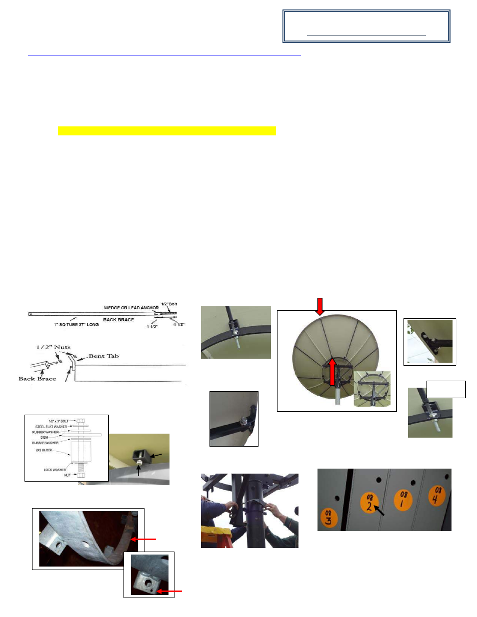
Be sure to lock the mount with ratchet straps once in birdbath position. (See
picture C, birdbath below)
STEP 1: Install the brace clips to the back braces before placing on the antenna lip and ring. Have all 8 brace clips installed on the
brace before going to the next step. See brace clip and back brace photos below. (details to install in Step 2)
STEP 2: Install brace clips to the ends of the 8 back braces and install the ½” nut on the threaded rod end of the back brace, threading
it down approximately 4 to 4 ½” down the threaded rod (see FIG. #13 and #14).
STEP 3: Take the first panel and install it to the ring of the mount finger tight. Be sure to find the pilot hole on the mount and on the
antenna. The pilot hole is located on the 2
nd
block from the left of the weld on the ring from the back view of the antenna.
The pilot
holes are used for a starting point only.
(see picture D). Take the back brace that is ready and put the threaded rod through the tab on the
ring (see picture A). Take the other end of the rod with the clip and attach the brace and clip to the lip of the antenna section
(see
picture B).
STEP 4: Insert ½” x 3” bolt from the antenna to the mount. (see FIG. #17) TIP: To assist on holding the rubber washer placed
between the block and the antenna we suggest using a piece of electrical tape to hold the rubber washer to the block.
Have one person continue holding the panel in place while the second person attaches the back brace. (Remember the threaded end of
the back brace should already have the ½” nut on the threaded end about 4-4 ½” on the threaded rod and the bent tab already installed
on the ring, see FIG. #15). Insert the threaded rod of the back brace into the bent tab and bolt brace clip on the edge of the antenna
with 1/4” x 3/4” bolt, 1/4” nut and 1/4”lock washer. Make sure everything is finger tight.
STEP 5: Pick up the second antenna panel and be sure the numbers line up and bolt in place just like the first panel. (see FIG. #9)
Once secure you can begin bolting the two units together by placing the ¼” x ¾” bolts through the templates. Again only finger tight.
Continue for remaining panels.
STEP 6: You will notice all 8 bolts in the face of the antenna have been installed from the antenna to the ring at this point. You now
remove every other bolt from the face of the antenna and replace them with a feed strut. (See preparing the feed assembly on page 6)
FIG. #13
PICTURE A
PICTURE B
FIG. #17
FIG. #15
Back braces are measured by tube
length only.
Page 4A
FIG. # 9
Brace Clip
Brace Tab Threaded
PICTURE C
PICTURE AA
48” Ring
1/2” x 1 1/2" Bolt
Match 2 with 2
See: DH Satellite YouTube Video
Fig 14
Block
1/2” x 3” Bolt
PICTURE B
PICTURE D
Pilot Hole
Weld