I/o connectors, Chapter 4 – DFI KS210-IMX6 Manual User Manual
Page 26
www.dfi .com
26
Chapter 4 Ports and Connectors
Chapter 4
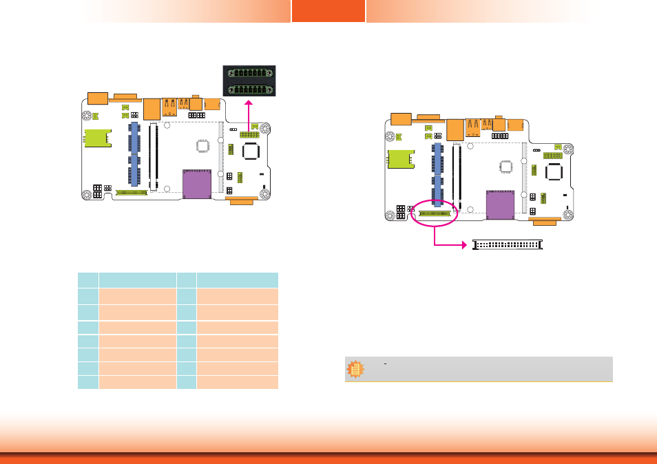
8-bit GPIO
1
7
8
14
The 8-bit Digital I/O (4-bit input and 4-bit output) connector provides powering-on function to
external devices that are connected to these connectors. The pin functions of the digital I/O
connector are listed below:
Pins
Function
Pins
Function
1
DIO_OUT-1
8
DIO_IN-4
2
DIO_IN-1
9
DIO_OUT-5
3
DIO_OUT-2
10
DIO_IN-5
4
DIO_IN-2
11
DIO_OUT-6
5
DIO_OUT-3
12
DIO_IN-6
6
DIO_IN-3
13
DCDC_5V_BB
7
DIO_OUT-4
14
GND
I/O Connectors
LVDS LCD Panel Connector
The system board allows you to connect a LCD Display Panel by means of the LVDS LCD panel
connector transmitting video signals and power from the system board to the LCD Display
Panel.
Refer to the next page for the pin functions of the connector.
Jumper Settings
Refer to the “Jumper Settings” section in chapter 3 for settings relevant to the LVDS LCD
panel.
LVDS LCD Panel
2
1
40
39
Note:
DFI board's LVDS connector: Hirose DF13-40DP-1.25V(91)/40P/1.25mm; cable side
connector: Hirose DF13-40DS-1.25C.