Chapter 3 - jumper settings, Jumper settings - system board, Chapter 3 chapter 3 - jumper settings – DFI KS210-IMX6 Manual User Manual
Page 15
www.dfi .com
15
Chapter 3 Jumper Settings
Chapter 3
Chapter 3 - Jumper Settings
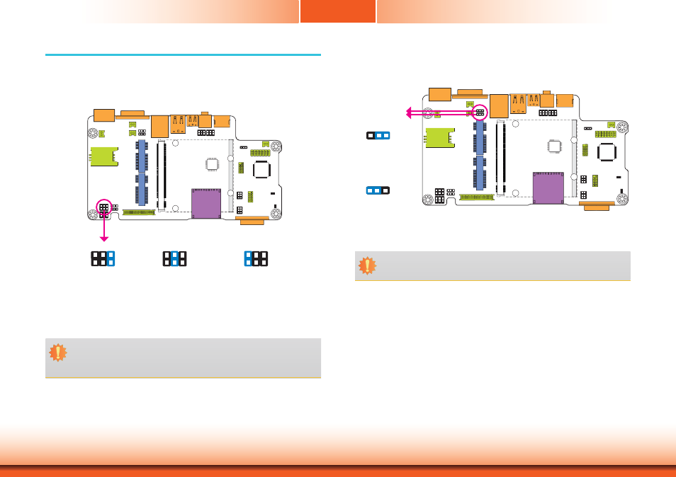
JP2
JP2 is used to select the power supplied with the LCD panel.
Important:
Before powering-on the system, make sure that the power settings of JP2 match the
LCD panel’s specification. Selecting the incorrect voltage will seriously damage the
LCD panel.
1-2 On: +12V
3-4 On:+5V_standby
5-6 On: +3V_standby
(default)
1
6 4 2
5 3
1
6 4 2
5 3
1
6 4 2
5 3
COM RS232/UART5 Select
JP11
JP12
1-2 On:
RS232 (default)
2-3 On: UART5
1
3 2
1
3 2
JP11 and JP12 are used to configure the COM port to RS232 (default) or UART5.
Important:
You need to set JP11 and JP12 simultaneously.
Jumper Settings - System Board
Panel Power Select
This manual is related to the following products: