Removing the chassis cover, Chapter 2 – DFI KS210-IMX6 Manual User Manual
Page 11
www.dfi .com
11
Chapter 2 Installing the Devices
Chapter 2
1. Make sure the system and all other peripheral devices connected to it have been powered-
off.
2. Disconnect all power cords and cables.
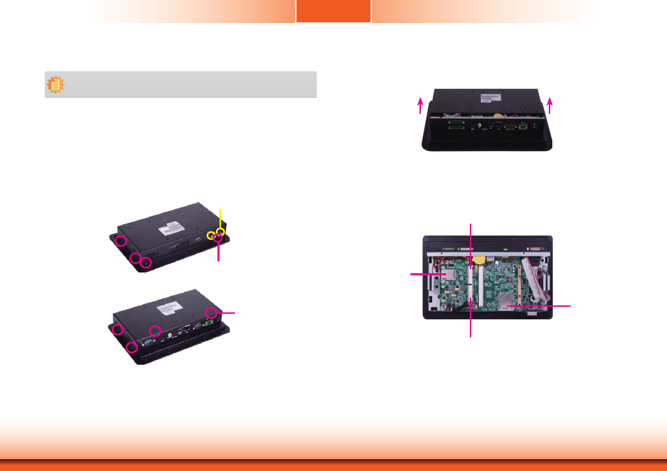
3. The 8 mounting screws on the side and cover of the system are used to secure the cover
to the chassis and the 2 mounting screws are used to fix the COM port. Remove these
screws and then put them in a safe place for later use.
Removing the Chassis Cover
Mounting Screw (COM port)
Mounting Screw
Mounting Screw
4. After removing the mounting screws, lift the cover up.
Lift the Cover Upward
5. 1 SIM card socket, 1 SD card socket, 1 mSATA slot and 1 Mini PCIe slot are readily acces-
sible after removing the chassis cover.
Mini PCIe Slot
SIM card socket
SD card socket
mSATA Slot
Note:
The system unit used in the following illustrations may not resemble the actual one.
These illustrations are for reference only.