3 end-user configuration, Port connection setup, 4 user interface – Daktronics ScoringTiming Interface (DSTI) User Manual
Page 10: End-user configuration, User interface
4
DSTI Setup
2.3 End-User Configuration
Port Connection Setup
Make sure all cables are routed from every device that will interface with the DSTI computer.
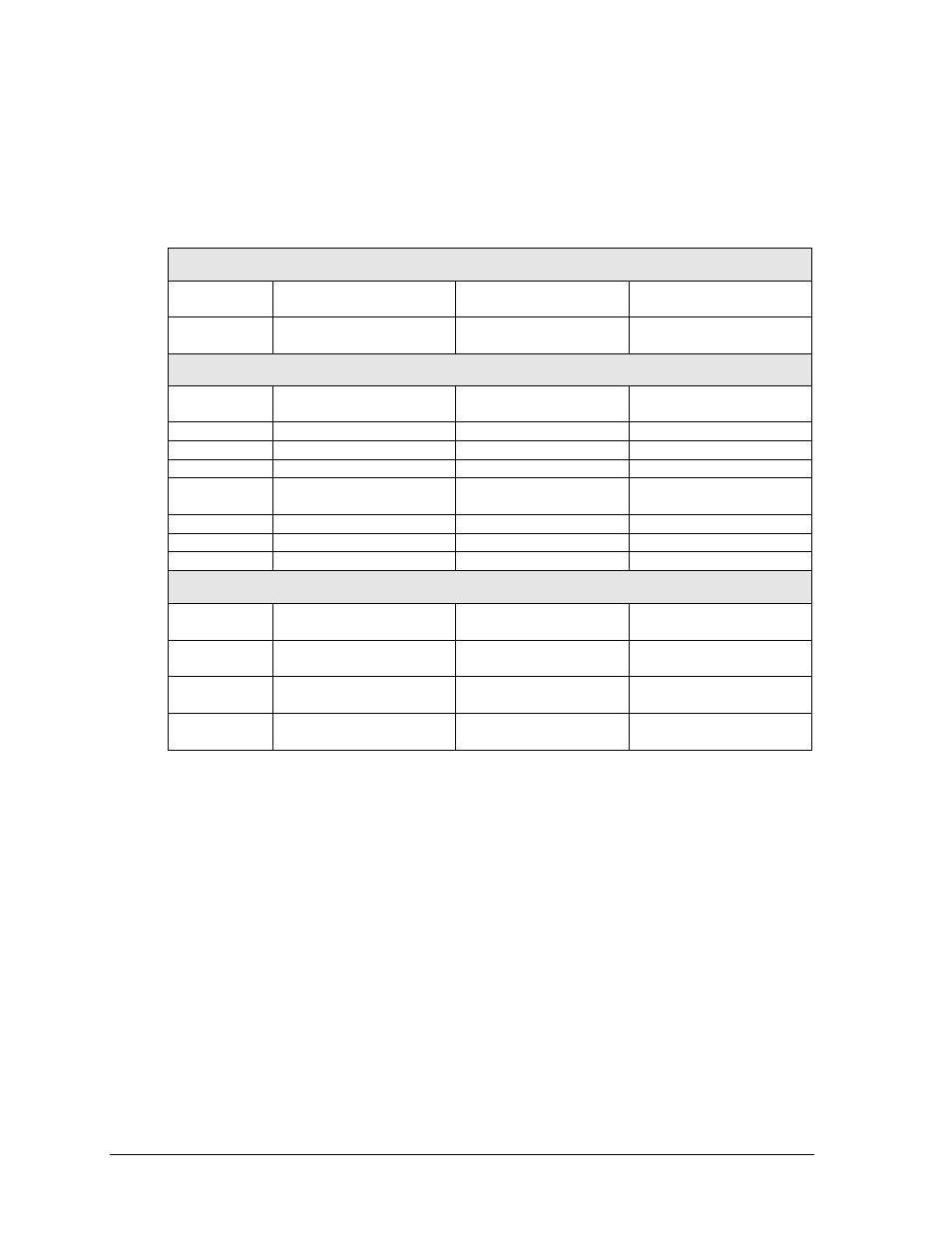
Use the table below to ensure the proper ports are being connected to the correct system.
Standard Port Connection Setup
COM Ports
DSTI
– Stand Alone
DSTI
– Sports Wire
DSTI
– Venus 7000
Software
COM 1
Game In Progress
(GIP) All Sport 5000
Game In Progress
(GIP) All Sport 5000
Game In Progress
(GIP) All Sport 5000
Rocket Port
COM 5
Stats Input
(IDS, StatCrew)
Stats Input
(IDS, StatCrew)
Stats Input
(IDS, StatCrew)
COM 6
Stats Output (IDS)
Stats Output (IDS)
Stats Output (IDS)
COM 7
TV Feed (GIP)
TV Feed (GIP)
TV Feed (GIP)
COM 8
Open
Wire Service
VLink
®
Processor
COM 9
Open
Open
ProStar
®
Display
Diagnostics
COM 10
Open
Open
Open
COM 11
Open
Open
Open
COM 12
Open
Open
Open
Network
UDP/IP-
20000
Open
Sports Wire RTD
Open
UDP/IP -
21000
GIP Real-Time Data
(RTD)
GIP Real-Time Data
(RTD)
GIP Real-Time Data
(RTD)
UDP/IP -
21321
Scoreboard Stats RTD
Scoreboard Stats RTD Scoreboard Stats RTD
UDP/IP -
21322
Requested Stats RTD
Requested Stats RTD
Requested Stats RTD
Notes: ProStar Display Diagnostics is not a necessity in Venus 7000 software connections.
Four-port Rocket Ports are the standard equipment, but 8-port Rocket Ports are available.
2.4 User Interface
The DSTI interface is composed of four main areas (Figure 3).
The Menu Bar allows some peripheral equipment manipulation and setup such as
print layouts and enabling the HTTP server.
The Button Panel allows sport and stats system selection and view options.
The Message Log displays information about how the interface is operating,
including any errors or status messages.
The Viewer Window shows input/output configurations and currently received
data from the stat software.