Daktronics AF-3090-89-R,A User Manual
Page 24
Electrical Installation
3-9
3.9
Optional Temperature Sensor Electrical Installation
Reference Drawings:
Temp Sensor Mounting .............................................................................Drawing A-79767
Signal Input, Venus 1500.........................................................................Drawing A-129110
After mounting the optional sensor, follow these steps to complete the electrical installation. A 2-pair,
individually shielded cable (Belden 5594, Daktronics part number W-1234) is used to connect the
sensor to the controller.
1. Run ½
″
conduit from the sensor location to the controller within the display. The cable must be
routed through one-foot of ½
″
metal conduit that should be earth-grounded to protect the sensor
and controller from lightning damage.
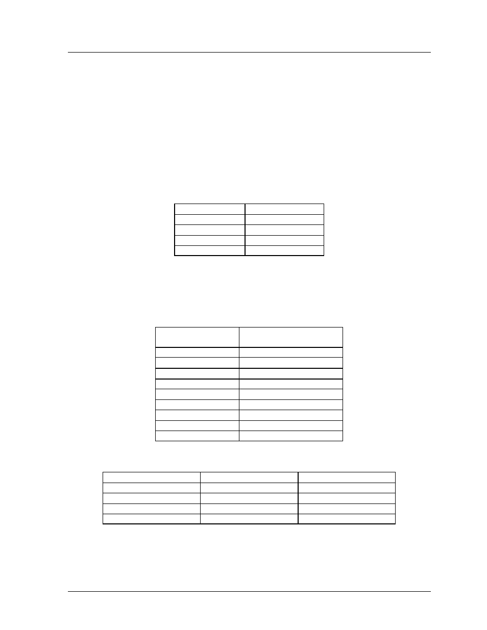
2. Connect the cable to the temperature sensor terminal block within the temperature sensor as
follows:
Wire Color
Terminal Block
Red
V+
Green
P
Black
GND
White
N
3. Install the mesh screen with the four screws enclosed.
4. Disconnect power to the display before attaching the cable.
5. Connect the cable to the temperature sensor terminal block on the controller (TB7) per the
following table:
Wire Color
Terminal Bock TB7
(Temp In)
Pin 1 (+5V)
Pin 2 (GND)
Pin 3 (Light +)
Pin 4 (Light -)
Green
Pin 5 (Temp +)
White
Pin 6 (Temp -)
Red
Pin 7 (+5V)
Black & Shield
Pin 8 (GND)
Or Bare (Shield)
Pin 8 (GND)
To connect the temperature sensor to multiple displays (such as a double -face display):
Wire Color
Display 1 TB7
Display 2 TB7
Green
Pin 5 (Temp +)
Pin 5 (Temp +)
White
Pin 6 (Temp -)
Pin 6 (Temp -)
Red
NC
NC
Black
NC
NC
Note: GND and +5V (Red and Black) are connected from the temp sensor to the first display
only. The Red and Black wires must not be connected between controllers in additional
displays.