Daktronics AF-3090-89-R,A User Manual
Page 22
Electrical Installation
3-7
3.7
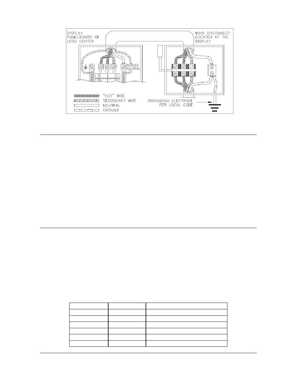
Main Disconnect
The National Electrical Code requires the use of a lockable power disconnect near the sign. Provide a
lockable disconnect switch (knife switch) at the sign location so that all power lines can be completely
disconnected. Use a 3-conductor disconnect to disconnect both hot lines and the neutral. Mount the
main disconnect at or near the point of power supply connection to the sign. Provide a main
disconnect for each supply circuit to the sign.
You must locate the means of disconnection in a direct line of sight from the sign or outline lighting
that it controls. This requirement provides protection by enabling a worker to keep the disconnecting
means within view while working on the sign.
Exception: You may locate the disconnecting means that are capable of being locked in the open
position elsewhere.
3.8
Signal Termination from Computer to Sign
Reference Drawings:
AF-3090 Controller Assembly, RS232/422 .............................................Drawing A-158254
AF-3090 Controller Assembly Modem ....................................................Drawing A-162098
AF-3090 Controller Assembly Fiber ........................................................Drawing A-162099
Schematic, AF-3090-8-32x***-24, Mono ................................................ Drawing B-161855
RS/232
One end of the signal cable should be terminated to the 6-position terminal block on the controller
labeled “RS232 IN” (TB1). The opposite end is terminated at the J-box near the display. The
controlling computer connects to the J-box through the serial cable.
J-Box
Field Cabling Terminal Block TB1 (RS232 IN)
Pin 1 (RTS)
Pin 2 (GND)
Pin 2 (RX-P)
Clear
Pin 3 (TX-P)
Pin 3 (GND)
Shield
Pin 4 (GND)
Pin 1 (TX-P)
Black
Pin 5 (RX-P)
Pin 6 (DCD)
Figure 19: Installation with only Neutral Conductor Provided