Daktronics AF-3090-89-R,A User Manual
Page 23
Electrical Installation
3-8
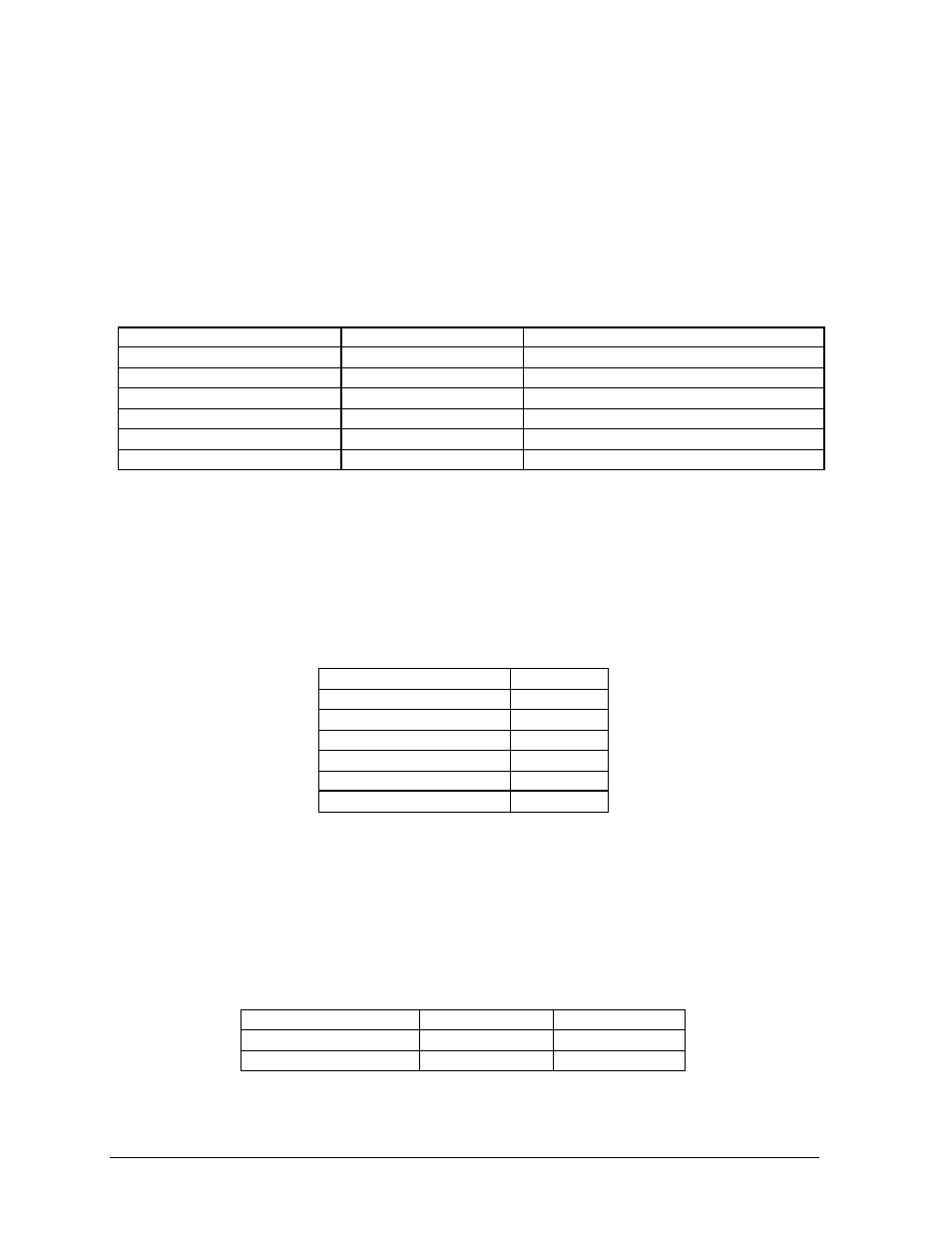
RS/422
One end of the signal cable should be terminated to the 6-position terminal block in the display
labeled “RS422 IN” (TB2). The opposite end is terminated at the signal converter (Daktronics part
number 0A-1127-0237) in the control room.
Note: RS422 cable must be installed so that it is separated from any source of electrical interface.
A minimum of a two foot separation between the signal cable and any power conductors is
typically required, or the signal cable may be routed in grounded metallic conduit. The signal
cable must not be routed in the same conduit as the power conductors.
Signal Converter (J4/J5)
Field Cabling
Surge Supressor, TB1 (RS422 IN)
Pin 1 (GND)
Red
Pin 1 (GND)
Pin 2 (RX-P)
Black
Pin 2 (TX-P)
Pin 3 (RX-N)
Brown
Pin 3 (TX-N)
Pin 4 (TX-P)
White
Pin 4 (RX-P)
Pin 5 (TX-N)
Blue
Pin 5 (RX-N)
Pin 6 (GND)
Green/Bare (Shield)
N.C.
Modem
In a display that uses a modem, Signal In routes first to a telecommunications connector and
terminated per the table below. A 6-conductor phone cord with RJ11 connectors (part number 0A-
1137-0160) relays the signal to the modem. A second phone cord (0A-1137-0160) transfers the
data from the modem to J1 (RS232 IN) on the controller.
Terminal Block TB31
Function
Pin 1
Pin 2
Pin 3
TIP-P
Pin 4
Ring-P
Pin 5
Pin 6
Fiber Optic
When the fiber optic cables are used, signal from the converter enters the fiber board (J4/J5). An
adapter module (Daktronics part number 0A-1146-0029) allows the use of a 6-conudctor-phone
cord with RJ11 connectors (par number 0A-1137-0160) to relay the signal to J1 (RS232 IN) on
the controller.
Signal Converter
Field Cabling
Sign A Data In
J2 (TX1)
J5 (RX2)
J3 (RX1)
J4 (TX2)