Replacing a driver, Setting the driver address – Daktronics ST-2000 Tuff Sport & ColorSmart LED Scorer’s Table User Manual
Page 22
16
Troubleshooting
Replacing a Driver
If the driver status indicators do not appear to be working correctly, it may be necessary to
replace the driver.
1. Open the table from the rear as described in Section 3.2.
2. Disconnect all connectors from the driver by squeezing together the locking tabs and
pulling the connectors free.
Note: It may be helpful to label the cables to know which cable goes to which
connector when reattaching the driver.
3. Remove the wing nuts securing the driver to the driver tray.
4. Carefully lift the driver from the display and place it on a clean, flat surface.
5. Position a new driver over the screws and tighten the nuts.
6. Reconnect all power/signal connectors.
Note: The connectors are keyed and will attach in one way only. Do not attempt to
force the connections.
7. Ensure the driver is set to the correct address (refer to Setting the Driver Address).
8. Close and secure the access panel, then power up and test the scoreboard to see if
changing the driver has resolved the problem.
Setting the Driver Address
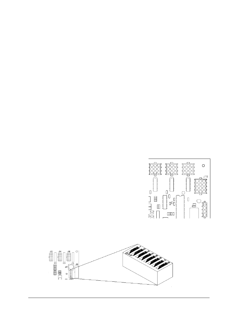
For the scoreboard to receive signal and function
properly, the driver must be set to the correct address.
All scoreboard tables in this manual use address 17.
This address is set with jumper wires in a 12-pin plug
which mates with jack J19 on the driver (Figure 16).
Refer to Drawing A-115078 for a listing of the wire/pin
connections for driver addresses 1 – 128.
ColorSmart scorer‟s table drivers also have the option
of setting the address using the S1 dip switch on the
driver (Figure 17) using a pen or small, pointed object.
Refer to Drawing A-290261 for addressing information
for driver addresses 1 – 128.
Figure 16: J19 Address (LED Driver II)
Figure 17: Driver Address Dip Switch (ColorSmart Driver)