Possession indicator, Light strip kit – Daktronics ST-2000 Tuff Sport & ColorSmart LED Scorer’s Table User Manual
Page 12
6
Mechanical Installation
2. Lift the table counter top approximately 90 degrees and swing the side legs out and into
place underneath. Use the locking slots to secure.
Note: It may be helpful to have two people perform this procedure: one to lift and hold
the table counter top and another to position and lock the legs in place.
3. Press down on the leg stops to make sure the table is level on both sides. For further
stability, also lock the rear table wheels.
4. Connect the twist lock power cord to the power-in plug in the lower-right corner of the
scorer‟s table, and then connect the plug to a grounding-type power outlet.
5. Set an All Sport 5000 or 5500 control console on the counter top and plug the power cord
into one of the 4 convenience outlets.
6. Connect the ¼" signal cable from J1, J2, or J3 on the control console to the All Sport signal
jack located between the first and second convenience jacks. If there are multiple tables
with LED light strips, also connect the appropriate signal cables (refer to Light Strip Kit).
7. Power on the control console and enter the appropriate sport code (found on the
keyboard overlay and in All Sport manuals).
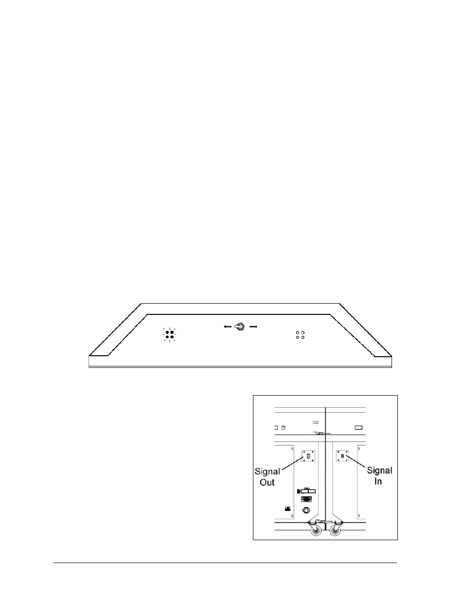
Possession Indicator
Daktronics scorer‟s tables may have an optional possession indicator that sits atop the table
padding. These are factory installed and require no additional setup. To operate, simply flip
the switch on the back of the unit toward the side of the court that has possession, and the
LED indicators will illuminate on both the front and back of the unit (Figure 6).
Light Strip Kit
Daktronics scorer‟s tables may have optional
light strips running along the bottom front of the
table that illuminate at the end of the period.
These are factory installed and require no
additional setup.
However, if multiple tables featuring light strips
are to be connected together, any additional light
strips will be controlled via 3-pin XLR cables
running between the tables. Refer to Figure 5 for
the location of the XLR input and output jacks.
Figure 5: Light Strip Input / Output Jacks
Figure 6: Possession Indicator Switch