Radio control, 3 power-on self-test (post), Radio settings – Daktronics ST-2000 Tuff Sport & ColorSmart LED Scorer’s Table User Manual
Page 13: Power-on self-test (post)
Display Specifications & Setup
7
Radio Control
Refer to Drawing A-1117167 in Appendix A for optional radio receiver installation
instructions. Then refer to Drawing A-1109105 for connection details to both Tuff Sport and
ColorSmart scorer‟s table drivers as well as how to set the radio Broadcast and Channel
settings. The radio settings must match those set in the control console (for more information
on radio settings, refer to the appropriate control console manual listed in Section 1.4).
Indoor radio systems have an optimal operating range of 20' – 500' between the control
console and the scoreboard(s). A radio-equipped All Sport console sitting directly on a radio-
equipped scorer‟s table is too close, and may decrease control reliability. The All Sport
console at the scorer‟s table location would work best to control other scoreboards via radio.
However, an All Sport console located elsewhere in the facility could control the scorer‟s table
or any other scoreboards that have radio receivers installed.
Note: If an All Sport console is to control the scoreboard(s) via radio and the scorer‟s
table too, there must be a wired signal to the scorer‟s table. Refer to Drawing B-168045
for installation instructions of the radio/wire switch (required for Tuff Sport models only;
ColorSmart scoreboards auto switch between wire and radio signal).
2.3 Power-On Self-Test (POST)
The scoreboard performs a self-test each time that power is turned on and the control console
is powered off or not attached to the scoreboard. If the control console is attached and
powered on, the self-test does not run, and data from the control console is displayed on the
scoreboard after a brief period of time. Each scoreboard self-test pattern will vary depending
on the scoreboard model, the number of drivers and types of digits. Figure 7 shows an
example of the LED bar test pattern that each digit performs.
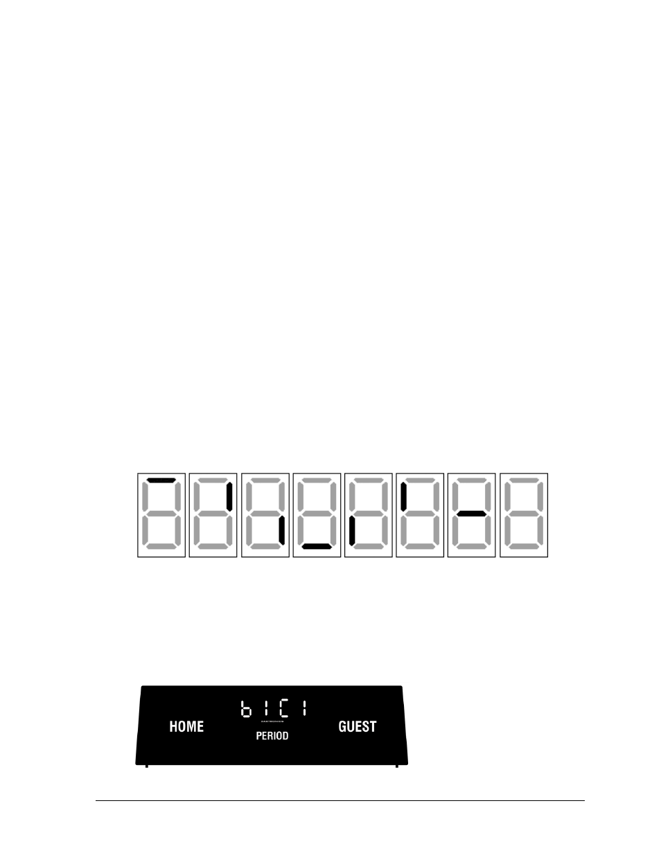
Radio Settings
If a radio receiver is installed, the radio broadcast settings (“b1”) and the channel settings
(“C1”) will be displayed in the clock digits (Figure 8) during the POST. These values must
match the settings in the control console (refer to the appropriate control console manual
listed in Section 1.4).
Figure 7: Digit Segment POST
Figure 8: Radio Settings in Clock Digits