Appendix, Pcb jumper locations – Cloud Electronics 46-50 User Manual
Page 24
46-50 Installation and User Guide V1.0
24
APPENDIX
PCB jumper locations
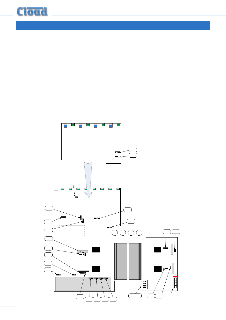
The 46-50 has various internal jumpers, the setting of which may require alteration during installation. The diagram below shows
the locations of the internal jumpers (not to scale) on the internal PCBs, and the table below lists each jumper and its purpose,
together with the factory default setting.
Note that the 46-50 has various sub-boards in addition to the main PCB. One of these, the music control sub-board, carries
two jumpers (J24 and J25), but all other jumpers are on the main PCB. Note that some main PCB jumpers are located below
this sub-board, and to access these, it is necessary to remove the sub-board. This can be done by disconnecting the three ribbon
cables linking the sub-board to elsewhere in the unit (two remain captive to the sub-board), removing the eight
SOURCE and
MUSIC LEVEL control knobs and shaft nuts, and then removing the three M3 screws at the rear of the sub-board.
Most jumpers have two possible positions; the black square in the symbol on the diagram below indicates the default setting.
If any jumpers need to be changed, turn the 46-50 off and disconnect it from the mains. Undo the eight screws securing the top
cover of the unit and remove it. Use a pair of small pliers to gently remove the jumpers from the PCB headers and reposition
them as required. Refit the top cover using the same screws.
The PCB diagram (which is as viewed from the rear of the unit) also shows the locations of the sockets for the optional
loudspeaker EQ cards (CON3, CON4, CON7 & CON8), resistor R220 (ref: Mic1-over-Mic 2 priority) and the Zone output
MUSIC CONTROL
SUB-BOARD
MAIN PCB
J3
LINE INPUT SUB-BOARD
J6
J5
J4
J24
J25
J1
J2
J20-J23
J15
J13
J14
J12
J18
J16
J7
J9
J19
J17
J8
J10
J11
CON 3
CON 4
CON 7
CON 8
Connectors for
CXL4160 transformer
assy.
Approx. location
of R220