Using the facility port as an auxiliary zone input, Fitting loudspeaker eq cards, Fitting the cxl-4160 transformer module – Cloud Electronics 46-50 User Manual
Page 22: Music source
46-50 Installation and User Guide V1.0
22
Music source
Music source for a zone may be controlled by applying
various DC voltages of between 0 and +10 V to pin 3, the 0 V
reference being connected to pin 1. 0 V at pin 3 will select Line
input 6 and between +7.5 and +9 V will select Line input 1.
The other line inputs will be selected with intermediate
voltages. Taking pin 3 above +9 V will deselect all inputs,
making the zone effectively ‘off’ for music.
The table below lists the DC voltages required at pin 3 to
select each line input. The third column is the value of a
resistor which should be connected between pins 1 and 3 to
permanently ‘force’ a zone to a particular line input.
INPUT
DC VOLTAGE
RESISTOR VALUE
OFF
>+9.0 V
Line 1
+7.5 V
16k
Line 2
+6.0 V
11k
Line 3
+4.5 V
6k8
Line 4
+3.0 V
3k9
Line 5
+1.5 V
1k8
Line 6
0 V
short-circuit
Note that there is an internal 15k “pull-up” resistor between
pin 3 and the internal +15 V rail. If pin 3 is left “floating”, this
pull-up will cause ‘OFF’ to be selected. The output impedance
of the control voltage source should be low enough to
overcome the effect of this resistor.
Using the Facility Port as an auxiliary
zone input
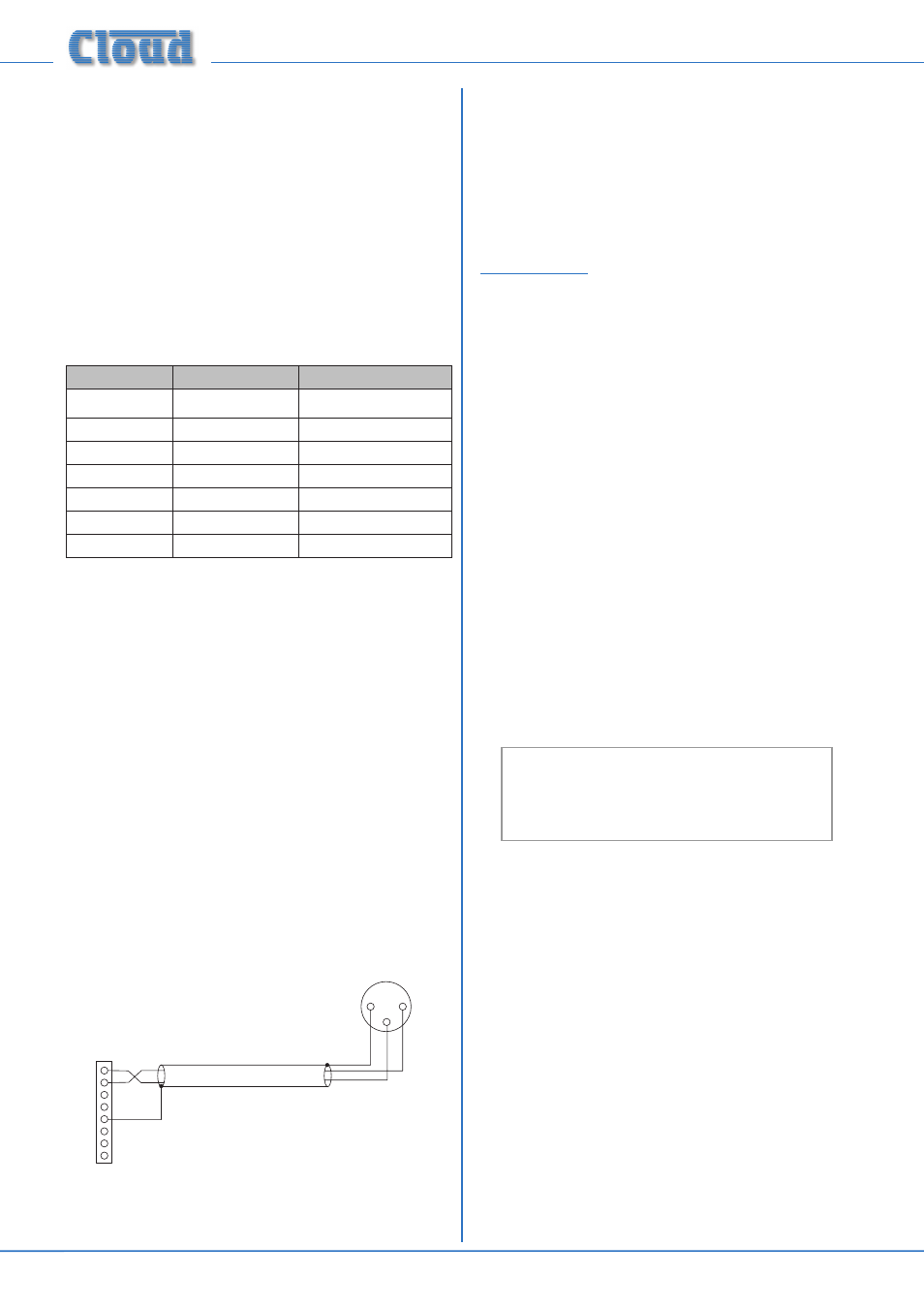
The Facility Port provides a balanced audio input. If a port is
not connected to an active remote module, it may be used as
a direct input to Zone 1 from other equipment forming part
of the system (for example, a permanently installed DJ mixer
which only ever needs to route its output to Zone 1.)
Wire an external balanced source to the facility port as
shown below:
1
8
7
6
5
4
3
2
1
3
2
BALANCED
OUTPUT (e.g. XLR)
hot (+)
ho
t(+)
cold (-)
col
d
(-)
1
8
1
8
1
8
46-50 ZONE 1
FACILITY PORT (RJ45)
An unbalanced source may also be connected; the use of
balancing transformers is recommended
Fitting loudspeaker EQ cards
The 46-50 is compatible with various popular installed-sound
loudspeakers; a single-channel loudspeaker equalisation
module may be fitted to any or all of the four outputs as
required, to optimise the frequency response of the channel
to the loudspeaker type being used.
The cards may be obtained from Cloud Electronics as
optional accessories. Please check the Cloud website
(
www.cloud.co.uk
) for makes and models of loudspeakers for
which compatible EQ cards are available.
To install equalisation modules, first disconnect the
46-50 from the AC mains supply, then remove the top
cover (8 screws). The modules plug into the white 12-pin
in-line sockets labelled CON3 (Zone 1), CON4 (Zone 2),
CON7 (Zone 3) and CON8 (Zone 4) on the main PCB.
Refer to the main PCB layout diagram at page 24, and
proceed as follows:
1. For each of the channel(s) having the EQ cards fitted,
remove the factory jumper adjacent to the 12-pin socket
as follows: J8 (Zone 1), J10 (Zone 2), J17 (Zone 3) and
J19 (Zone 4). We recommend leaving the jumper on one
pin to avoid losing it.
2. Plug the EQ card into the 12-pin socket, pressing gently
until it clicks into place. Note the mating connector on
the module has two small projections which engage with
two notches on one side of the socket, to aid orientation.
3. Replace the top panel using the same screws.
Fitting the CXL-4160 transformer
module
NOTE: Full installation instructions are included
with the transformer module.
The notes below are an abridged version.
The CXL-4160 transformer allows the 46-50 to be used with
100/70 V-line loudspeaker systems.
1. Disconnect the 46-50 from the mains and remove the
top cover.
2. Remove the blanking plate from the
100V/70V-LINE
OUTPUTS connector location on the rear panel;
retain the plate and screws, nuts and washers.
3. The CXL-4160 is preset for 70 V-line or 100 V-line
operation according to territory. If the alternative voltage
is required, change the solder links on the rear of the
CXL-4160 PCB.
4. Fit the module to the right-hand side of the 46-50
(viewed from the rear) by the eight hex spacers, using
the screws supplied. The rear connector should project
neatly through the vacated rear panel slot.
5. Plug the 8-pin connector on the flying lead assembly
(supplied) onto the 8-pin header on the CXL-4160 PCB.