Microphone input paging system connections, Microphone input, Paging system connections – Cloud Electronics 46-50 User Manual
Page 14: Connecting pm4/4sa paging microphones
46-50 Installation and User Guide V1.0
14
and some designs require different wiring protocols to others,
but to connect only the ‘hot’ and ‘screen’ to the unbalanced
input while leaving the ‘cold’ unconnected has been found to
work satisfactorily in many situations. However, in all cases,
installers are advised to check the manuals with each item
for guidance on how the outputs should be connected to an
unbalanced input.
Microphone input
Inputs
MIC 1 and MIC 2 are intended for the direct
connection of microphones. They are electronically balanced
and transformerless with an input impedance of greater than
2 kohms and optimised for use with microphones of 200 to
600 ohms impedance. The screw terminal input connectors
should be wired thus:
PIN
CONNECTION
1
Screen
2
Signal ‘-‘ (cold)
3
Signal ‘+’ (hot)
Unbalanced microphones may be used by connecting pin 2
to pin 1 (cable screen) in the mating (male) screw-terminal
connector. 15 V phantom power is available, see page 18.
Either mic input may be routed to any of the zones in use,
at any level in each zone. Microphone priority may be set
so that any microphone announcements automatically reduce
the music level in that zone while the announcement is in
progress (see page 19 for more details.)
Paging system connections
Cloud PM Series paging microphones may be connected
directly to the 46-50.
Two connections are required: the paging mic audio signal
should be connected to the
MIC 1 input ([3] on page 12)
and the control cable to the 6-pin
PAGING ACCESS port
([7] on page 12). The pinout of the
PAGING ACCESS
port is given below:
PIN NO. FUNCTION
1
0 V
2
Zone 1
3
Zone 2
4
Zone 3
5
Zone 4
6
+15 V
Connecting PM4/4SA paging microphones
These microphones are equipped with both digital and
analogue paging interfaces; with the 46-50, the analogue
interface is used. PM microphones are available in 4, 8, 12
or 16-zone versions; the installer should be sure he/she
understands how paging zones correspond to mixer zones
before commencing wiring. Although the 46-50 only supports
a maximum of four zones, there is no technical reason to
prevent a PM microphone being used in a restricted manner.
Standard two-core screened audio cable may be used for
the audio signal, and stranded multicore (6-core is suitable)
cable with an overall screen for the control cable. Note that
PM Series microphones may obtain their DC power from the
46-50, but SA versions and need an external PSU.
Connections on the PM microphone are made via the rear
cable access glands and screw terminal blocks on the main
internal PCB (TERM2 and TERM 8 in the case of a PM4).
Full connection details can be found in the PM Series
Installation and User Guide.
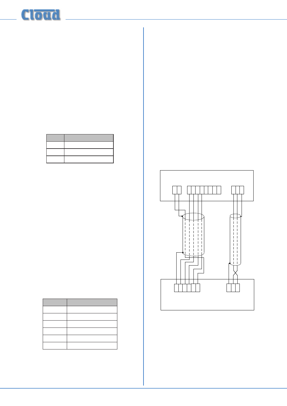
The diagram below shows the cable connections between a
PM4 and a 46-50, where power is supplied by the 46-50.
TERM8
TERM2
HOT COLDGND
Z1
Z2
Z3
Z4
MIC 1/TEL INPUT
Z1
Z2
Z3
0 V
PM4 PAGING MICROPHONE
46-50
Z5
Z6
Z7
Z8
TERM1
0V
+V
+V
Z4
1
3
2
ACCESS CONTACTS
Note that the default factory setting routes
MIC 1 to all
four zones at all times. In order for
MIC 1 to function
correctly with a paging mic, internal jumpers J23 (Zone 1),
J22 (Zone 2), J21 (Zone 3) and J20 (Zone 4) should be
removed to enable the
PAGING ACCESS connector.
See page 24 for jumper locations.
For automatic music ducking during an announcement,
internal jumper J12 must be in its ‘ON’ position.
See page 19 for further information.