Front panel description – Cloud Electronics 46-50 User Manual
Page 11
46-50 Installation and User Guide V1.0
11
Front panel description
0
1
SOURCE
SOURCE
SOURCE
SOURCE
MUSIC LEVEL
MUSIC LEVEL
MUSIC LEVEL
MUSIC LEVEL
MIC 2
MIC 1
LEVEL
1
2
3
4
5
6
HF
LF
0
10
10
10
0
-
dB
ZONE 1 MUSIC EQ
CLIP
MIC 2
MIC 1
LEVEL
1
2
3
4
5
6
HF
LF
0
10
10
10
0
-
dB
ZONE 2 MUSIC EQ
CLIP
MIC 2
MIC 1
LEVEL
1
2
3
4
5
6
HF
LF
0
10
10
10
0
-
dB
ZONE 2 MUSIC EQ
CLIP
MIC 2
MIC 1
LEVEL
1
2
3
4
5
6
HF
LF
0
10
10
10
0
-
dB
ZONE 2 MUSIC EQ
CLIP
ZONE 1
ZONE 2
ZONE 3
ZONE 4
4 ZONE 50W INTEGRATED
MIXER AMPLIFIER
3
5
6
9
4
1
9
8
2
7
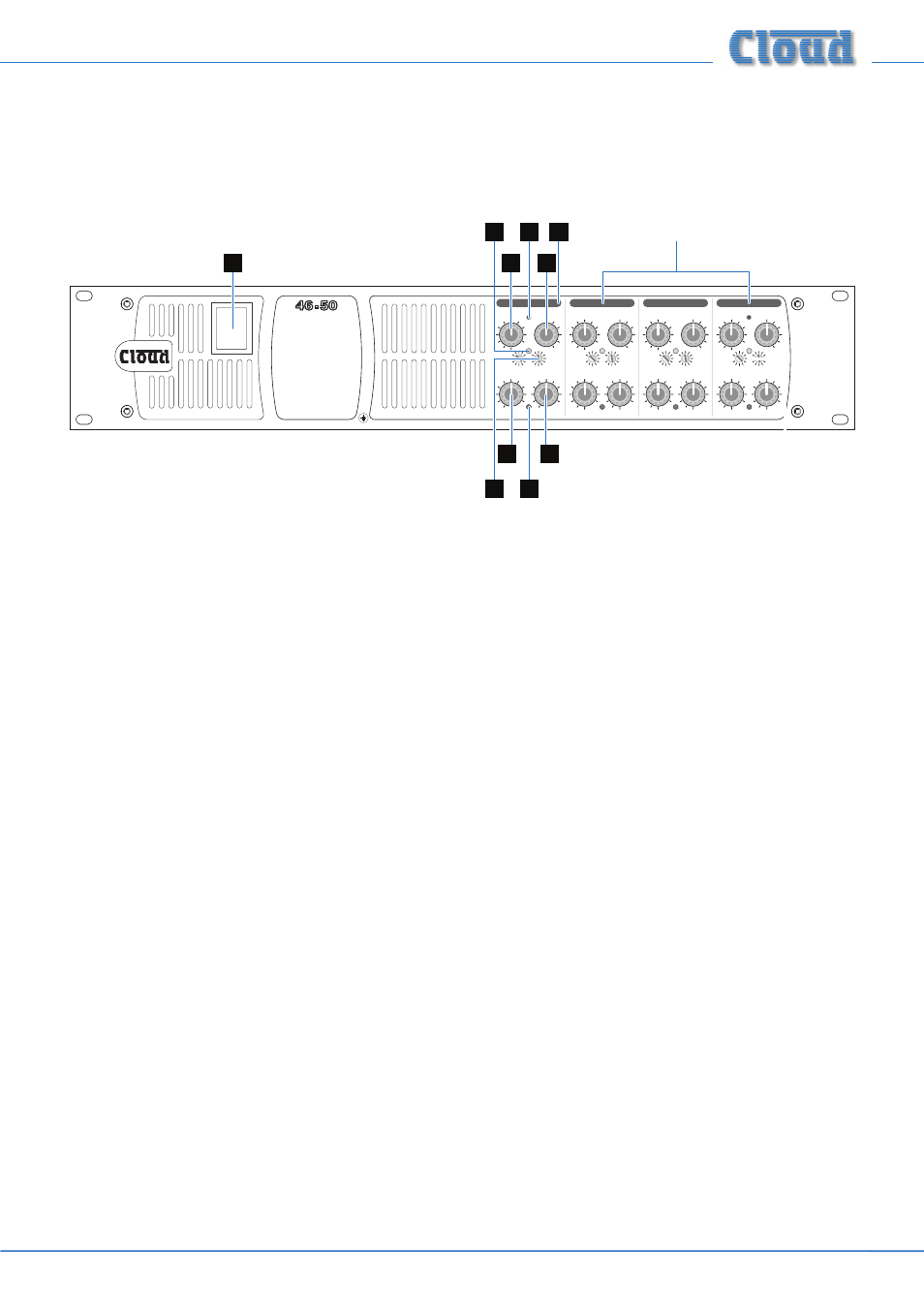
Only Zone 1 controls indicated;
those for the other Zones are identical.
1.
SOURCE – 6-way rotary switch selecting which Line Input (LINE 1 to LINE 6) will be the music source for each zone.
See page 18.
2.
MUSIC LEVEL – adjusts the music level in each zone. See page 18.
3.
MIC 1 – adjusts the level of the microphone connected to the rear panel MIC 1 input in each zone. See page 18.
4.
MIC 2 – as [3], but controls level of MIC 2 input.
5.
MUSIC EQ – two preset controls for adjusting HF/LF EQ in each zone. See page 18.
6.
CLIP – per-zone red LEDs; illuminate when the output stage’s Dynamic Clip Limiter is active. This indicates that the level
is too high.
7. Power – rocker switch.
8. Zone idents – a space is provided above each zone’s controls for printed labels identifying the zone by name.
9. Fixing holes for security cover – prevents access to Zone EQ controls.