Installation instructions, 63] for enhanced – BECKHOFF EL9xxx User Manual
Page 63
Mounting and wiring
5.2
Installation instructions for enhanced mechanical load
capacity
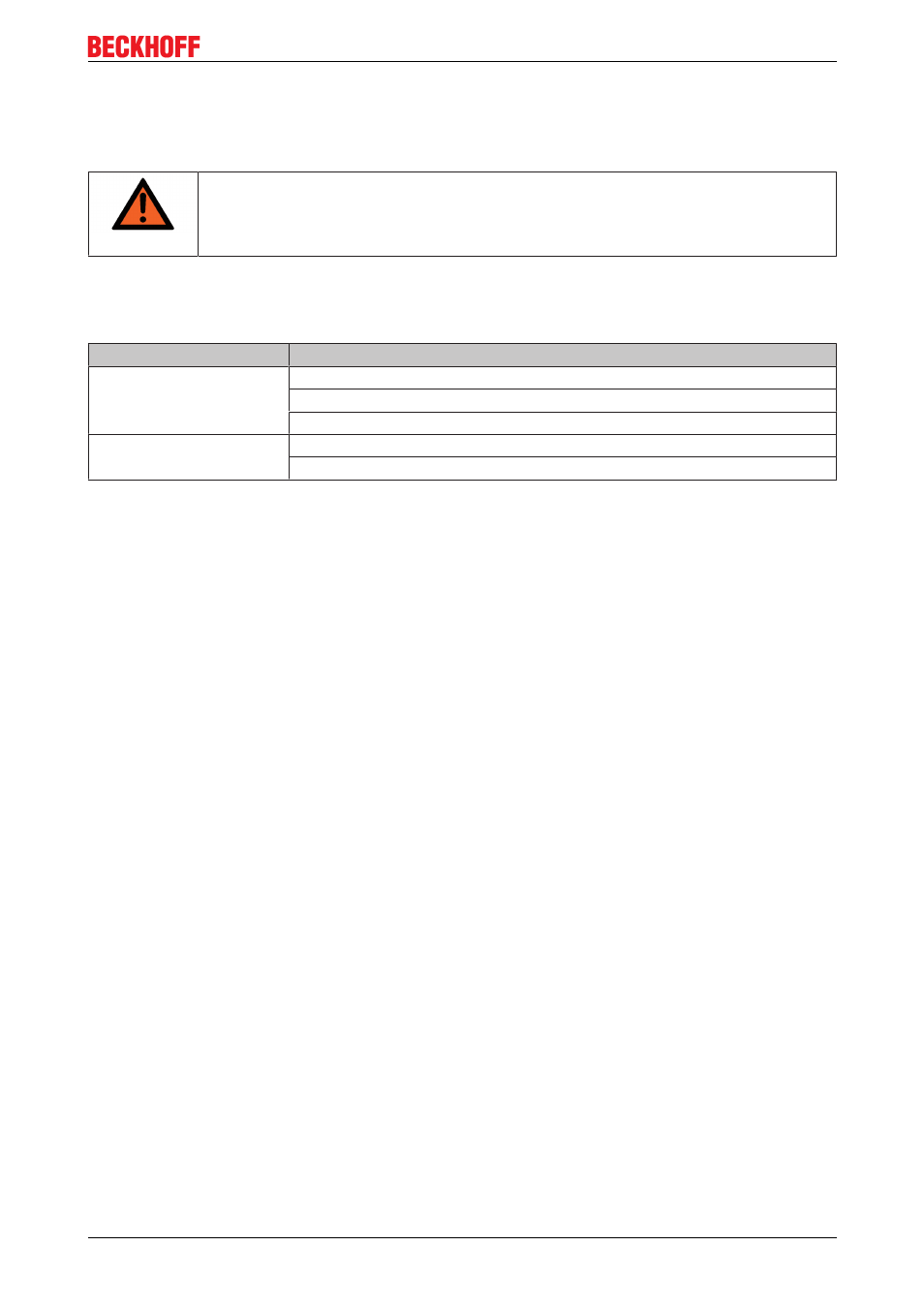
WARNING
Risk of injury through electric shock and damage to the device!
Bring the Bus Terminal system into a safe, deenergized state before starting mounting,
disassembly or wiring of the Bus Terminals!
Additional checks
The terminals have undergone the following additional tests:
Verification
Explanation
Vibration
10 frequency runs in 3 axes
6 Hz < f < 60 Hz displacement 0.35 mm, constant amplitude
60.1 Hz < f < 500 Hz acceleration 5 g, constant amplitude
Shocks
1000 shocks in each direction, in 3 axes
25 g, 6 ms
Additional installation instructions
For terminals with enhanced mechanical load capacity, the following additional installation instructions apply:
• Any installation position is permitted
• Use a mounting rail according to EN 60715 TH3515
• Fix the terminal segment on both sides of the mounting rail with a mechanical fixture, e.g. an earth
terminal or reinforced end clamp
• The maximum total extension of the terminal segment (without coupler) is:
64 terminals (12 mm mounting with) or 32 terminals (24 mm mounting with)
• Avoid deformation, twisting, crushing and bending of the mounting rail during edging and installation of
the rail
• The mounting points of the mounting rail must be set at 5 cm intervals
• Use countersunk head screws to fasten the mounting rail
• The free length between the strain relief and the wire connection should be kept as short as possible. A
distance of approx. 10 cm should be maintained to the cable duct.
EL9xxx
63
Version 3.1