BECKHOFF EL9xxx User Manual
Page 44
Product overview
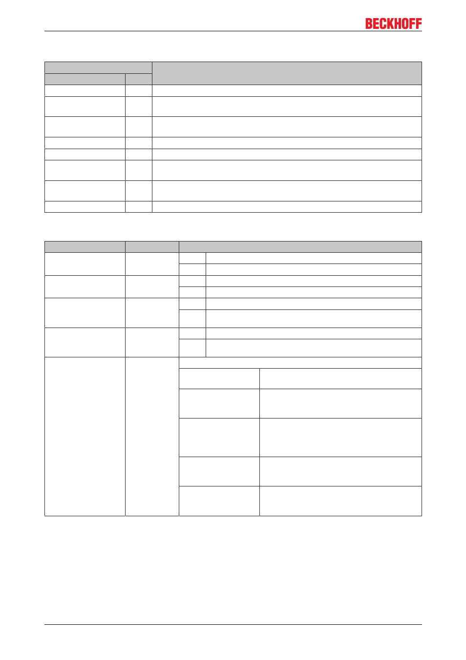
Connection EL9400, EL9410
Terminal point
Description
Indication
No.
+24 V for EBus
1
Supply input + 24 V for the EBus
+24 V
2
Supply input + 24 V (connected internally with terminal 6 and positive power
contact)
0 V
3
0 V for supply input (connected internally with terminal 7 and negative power
contact)
PE
4
PE (connected internally with terminal 8)
0 V for EBus
5
0 V for supply input EBus
+24 V
6
Supply input + 24 V (connected internally with terminal 2 and positive power
contact)
0 V
7
0 V for supply input (connected internally with terminal 3 and negative power
contact)
PE
8
PE (connected internally with terminal 4)
LEDs
LED
Farbe
Bedeutung
Power LED
(EBus)
green
off
No input voltage at supply input for the EBus
on
24 V
DC
at supply input for the EBus
Power LED
(Power Contacts)
green
off
No input voltage at supply input
on
24 V
DC
at supply input
Diagnosis LED**
Us
red
off
No error
on
Undervoltage: Us less than 17 V
Diagnosis LED**
Up
red
off
No error
on
Undervoltage: Up less than 17 V
RUN
green
This LED indicates the terminal's operating state:
off
State of the EtherCAT State Machine: INIT =
Initialization of the terminal
flashing (2 Hz)
State of the EtherCAT State Machine:
PREOP = Setting for mailbox communication
and variant standard settings
flashing (1 Hz)
State of the EtherCAT State Machine:
SAFEOP = Channel checking of the Sync
Manager and the Distributed Clocks. Outputs
stay in safe operation mode.
on
State of the EtherCAT State Machine: OP =
Normal operation mode, mailbox and
process data communication possible
flashing (10 Hz)
State of the EtherCAT State Machine:
BOOTSTRAP = Function for e.g. firmware
updates of the terminal
** only EL9410
Process data (only EL9410)
The EL 9410 has a bit width of 2 bits (diagnosis bits for the power contacts voltage [Up] and for the EBus
voltage [Us], 'Undervoltage') and is displayed in the TwinCAT tree as follows:
EL9xxx
44
Version 3.1