The interfaces, Power supply – BECKHOFF BK5200 User Manual
Page 8
Basic Principles
8
BK52x0
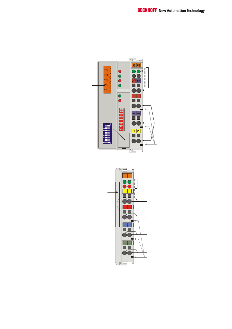
The interfaces
A Bus Coupler has six different methods of connection. These interfaces
are designed as plug connectors and as spring-loaded terminals.
The DeviceNet Coupler
BK5200 / BK5210
DeviceNet
OVERFL
RUN
BUS OFF
CONNECT
NS
MS
I/O RUN
I/O ERR
B
K
52
00
Power LEDs
Bus Coupler / Power
contacts
K-Bus
DeviceNet
connector
Configuration-
Interface
Power supply
Bus Coupler
24 V DC / GND
Input
Power contacts
Power contacts
The LC5200 Bus Coupler integrates the bus connection into the spring-
loaded terminals.
The DeviceNet coupler
LC5200
Power supply for
Bus Coupler
and field level
left:
fieldbus LEDs
right:
K-Bus LEDs
02
01
+
+
S
S
C+
C-
00
X0
LC5200
Beckhoff
K-Bus
CAN-H, CAN-L
V+
V-
Power contacts
Screen
Address
selector
Power supply
BK5200, BK5210:
24 V DC to the topmost
terminals “24 V” and “0 V”
The Bus Couplers require a 24 V DC supply for their operation. In the case
of the BK52x0 Bus Couplers the connection is made by means of the
upper spring-loaded terminals labelled “24 V” and “0 V”. This supply
voltage feeds not only the Bus Coupler electronics via the K-Bus, but also
the Bus Terminals. In the BK52x0 Bus Couplers the voltage supply for the
bus coupler electronics and that of the K-bus are electrically isolated from
the field level potentials.