BECKHOFF BK5200 User Manual
Page 31
Appendix
BK52x0
31
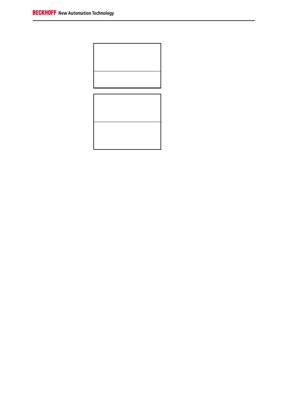
The distribution of the process image in the Bus Coupler in overview:
Output data in the Bus
Coupler
O0
...
byte-oriented data
...
A11
O12
bit-oriented data
O13
Input data in the Bus
Coupler
I0
...
byte-oriented data
...
E3
I4
...
bit-oriented data
...
I6
The base addresses I0 and O0 listed here are used as relative addresses
or addresses in the Bus Coupler. If you have an appropriate superordinate
DeviceNet system, you can use the bus master to enter these addresses at
any desired position in the controller's process image. You can use the
configuration software of the master to assign the bytes to the addresses in
the process image of the controller.