Connector pin assignment / devicenet connection, Power supply, Can-l v+ v- screen can-h – BECKHOFF BK5200 User Manual
Page 23
BK5200, BK5210, LC5200 DeviceNet
BK52x0
23
Connector Pin assignment / DeviceNet
connection
DeviceNet connection
BK5200, BK5210:
Bus power and terminal
power are supplied
separately.
Both power supplies must
be connected.
A 5-pin plug is supplied to connect the DeviceNet bus cable. When it is
plugged into the Bus Coupler, pin 1 is at the top. The figure shows the
socket in the Bus Coupler. The power supplied by this plug is isolated from
the power supply of the terminal to the right of the Bus Coupler. Both
power sources must be connected before the system can operate.
Pin assignment of DeviceNet
connection
1
V+
2
CAN-H
3
GND
4
CAN-L
5
V-
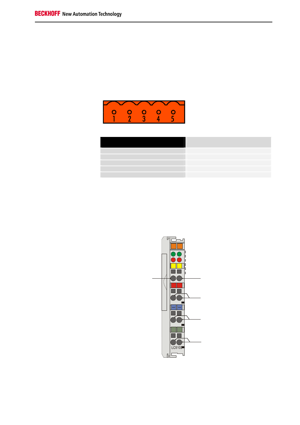
DeviceNet connection
LC5200
In the low cost LC5200 coupler, the CAN wires are connected directly to
the contact points 1 (CAN-H, marked with C+) and 5 (CAN-L, marked with
C-). V+ is placed on the terminal locations 2 and 6. V- is placed on the
terminal locations 3 and 7. The screen can optionally be connected to
contact points 4 or 8, which are connected to the top hat rail via an R-C
network.
Connection diagram for the
LC5200 Bus Coupler
Power supply
02
01
+
+
S
S
C+
C-
00
X0
Beckhoff
CAN-L
V+
V-
Screen
CAN-H
.