Data exchange – BECKHOFF BK5200 User Manual
Page 24
BK5200, BK5210, LC5200 DeviceNet
24
BK52x0
Data exchange
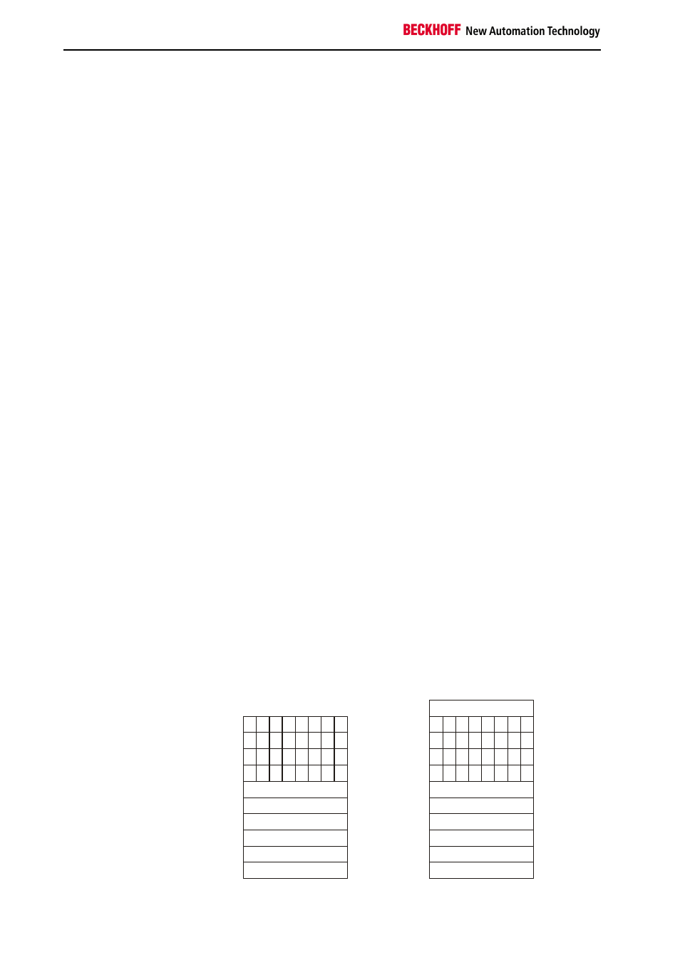
Data string from the
DeviceNet master to the
Bus Coupler:
first byte-oriented data, and
then bit-oriented data.
4 bytes for 2-channel
analog output terminals
2 bits for 2-channel digital
output terminals
First the data from all the
analog outputs
Then the data for the digital
outputs is transmitted in
bytes
Some of the bits in the last
byte may be unused
Data is transferred between masters and slaves in the form of objects. The
Bus Coupler recognises two objects: an input object and an output object.
You can use the configuration software to map the input/output bytes onto
specific memory areas in the controller. The Bus Coupler uses a consistent
algorithm to correlate the object data to the peripherals. Various examples
of correlations between addresses and peripherals are explained in the
appendix. A (data) object which is transferred from the DeviceNet master
to the Bus Coupler must begin with the byte-oriented values, which is the
data for the analog output terminals. The bit-oriented data for digital
outputs may not be transmitted until all the byte-oriented values have been
sent.
Analog outputs receive 16 bits of data, i.e. two bytes, for each channel. An
analog output terminal with 2 channels must therefore receive 4 bytes. A
digital output terminal with 2 channels needs a total of 2 bits of data, one
for each channel.
The first 4 bytes of an object which is transferred to the terminal strip are
assigned to the first analog output terminal, which is the analog output
terminal nearest to the Bus Coupler. Other terminals which are located
between the Bus Coupler and the first analog output terminals are
disregarded. The next four bytes of the object go to the second analog
output terminal in the terminal strip. Any other terminals between the first
and second analog output terminals are disregarded.
When the last analog output terminal in the terminal strip has received its
data, the digital outputs are served. Data is always transferred in the form
of bytes, so the next byte from the data string contains data for 8 digital
outputs. Bit 0 and bit 1 are assigned to channels 1 and 2 of the first digital
output terminal after the Bus Coupler. Other types of terminal which are
located in between are ignored.
Bits 2 and 3 go to the 2 channels of the second digital output terminal, bits
4 and 5 to the third and bits 6 and 7 to the fourth. There may be other
terminals located between these digital output terminals, and if so they will
be disregarded.
Additional bytes are read from the data string until the last digital output in
the terminal strip has been dealt with. If the total number of digital outputs
is not a multiple of 8, there will be a number of bits left over in the last data
byte; these will be discarded.
Byte 0
Byte 0
. . .
. . .
. . .
. . .
. . .
. . .
. . .
. . .
. . .
. . .
. . .
. . .
. . .
. . .
. . .
. . .
B
yt
e
da
ta
B
yt
e
da
ta
B
it
da
ta
B
it
da
ta
Byte n
Byte n
Status byte
Object from master to the Bus Coupler Object from Bus Coupler to the master